Download
1 / 30
300 likes | 445 Views
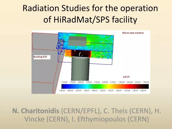
Radiation Studies for the operation of HiRadMat /SPS facility. N. Charitonidis (CERN/EPFL), C. Theis (CERN), H. Vincke (CERN), I. Efthymiopoulos (CERN). Introduction.

E N D
Radiation Studies for the operation of HiRadMat/SPS facility N. Charitonidis(CERN/EPFL), C. Theis (CERN), H. Vincke (CERN), I. Efthymiopoulos (CERN)
Introduction • Detailed Monte-Carlo studies, using the FLUKA code have been performed for severalpossible, operational, and worst-case scenarios for all the tunnels (TNC, TJ7, TA7, PA7) and surface buildings • HiRadMat radiation issues are very challenging, due to the nature of the facility • The activation and background radiation has been calculated for seven cooling times, up to 2 months • Specific calculations have been performed for the possible activation of the water-cooling circuit. • Apart from this presentation, an EDMS internal note is being prepared.
Geometry & drawings • The most challenging part was the implementation of the real tunnels and buildings geometry using FLUKA’s combinatorial geometry. • The drawings in some cases were really old and difficult to find. • It is not always possible to model all the details of the actual geometry using only simple shapes
A very detailed geometry BA7 2010 2010 TCC6 PA7 TJ7 TT61 TA7 TNC 2010 1975 Thanks to: I. Efthymiopoulos, A. Pardons, C. Magnier, O. Choisnet, S. Evrard, D. De Paoli for answering my numerous requests for drawings and details!
FLUKA model Stair-case and elevator holes Ventilation T9 dump (modeled by A. Christov) test stand + collimator Magnets & beam elements Bt. 876 Bt. BA7 • The dimensions of the tunnels and the “tunnel findings” are in almost perfect agreement with the drawings PA7 Bt. 846 • For the estimation of the BA7 dose, the PA7 geometry was modelled in detail (staircase and e/m installations)
Several Scenarios • Prompt studies (A copper target, 1m length, placed at focal point 1 (representing a worst-case scenario) • Activation studies (operational scenario with the table and the collimator placed in focal point 3) • Background studies (when the activated objects are removed, the remnant dose at the tunnel)
BA7 Geometry modeling Roof “blind” point BA7 roof Internal shaft room Bt. 876 Hole cover (Iron, 1cm) Soil around (standard compound composition) and natural air surrounding the buildings
BA7 Geometry modeling BA7, inside the internal shielding Iron plate covering the hole Staircase The cables and electromechanical infrastructure of the shaft The hole of the elevator installation.
Irradiation Parameters • For the worst case scenario a copper target of 3cm radius and 1 meter length, accepting the full beam. • The results by FLUKA are given in pSv/primary. So a normalisation factor of the following form was applied: • The worst beam scenario is 4.89E15 protons over 100 extractions of 20s each.
BA7: Prompt Dose 70-200 μSv/h On average < 0.5 μSv/h out of the internal wall The area outside the internal shielding can be characterized as “Non designated area” μSv/h Negligible prompt dose rates in all accessible areas
BA7 roof prompt dose • In case of some needed intervention during the facility operation in the BA7 building roof, the prompt dose rate was calculated. 1 – 10 nSv/h for the worst case scenario. Negligible μSv/h
BA7 roof prompt dose (“weak” point) Weak point on the roof of BA7. Negligible prompt radiation. Also the prompt radiation levels in building 876 are in compliance with a non-classified area .
TNC tunnel calculations - PROMPT Iron blocks Ventilation Copper target T9 dump Beam line elements 10-40kSv/h ~ 100 Sv/h Worst case scenario ( 4.89E15 protons over 100 extractions of 20s each). Prohibited area during operation
TNC tunnel calculations - Activation • Irradiation profile chosen : Short SPS cycle, 1.98E12 p/s for 504 s (~1e15 protons) • Seven cooling times: 1 hour, 1 day, 2 days, 1 week, 1 month, 3 months. • Exemplary operation scenario: The beam hits the carbon jaw of a typical collimator, placed on the test stand T9 The third stand table was modeled to be at focal point 3.
TNC tunnel - Activation • Cooling time of 1 hour 10-50 mSv/h μSv/h 1-5 mSv/h near the collimator • Cooling time of 1 day μSv/h
TNC tunnel - Activation 1mSv/h • Cooling time of 1 week μSv/h • Cooling time of 1 month 75μSv/h ~ 1 μSv/h nSv/h μSv/h
Near the collimator • Since interventions may be necessary near the activated object, some typical values are given: Dump Position “middle”: 40cm from the end of the collimator Position “downstream”:30 cm from the collimator Position “upstream”: 50 cm from the collimator Position “lateral”: 40 cm from the collimator Detailed model of the stand table.
TNC tunnel – Background dose • Using the latest version of the code, we calculated the background (remnant) dose at the tunnels, i.e when the activated object is removed • Again the same 7 cooling times where used. • Scenario: A “small” copper target (15 cm length) was placed at focal point 3 (closer to the dump), with an irradiation scenario of 1E16 protons over 1 year.
TNC Tunnel - Background • Cooling time of 1 hour ~ 150μSv/h ~ 5μSv/h μSv/h The contribution on the background dose is mainly from the activation of the dump • Cooling time of 1 day μSv/h
TNC Tunnel - Background • Cooling time of 1 month ~ 16 μSv/h μSv/h • Cooling time of 2 months μSv/h
TJ7 tunnel : Prompt Dose • Worst case scenario : 4.89E15 protons over 100 extractions of 20s each ~ 20 Sv/h ~ 40 Sv/h Access to TJ7 during operation : PROHIBITED ~5 Sv/h ~ 10 Sv/h • Even for the long SPS cycle (1E15 protons over 30 extractions of 44s each
TJ7 tunnel - Activation Dose • Same activation scenario as for the TNC tunnel - Short SPS cycle, 1.98E12 p/s for 504 s (~1e15 protons) – beam on the carbon jaw of the collimator • The same cooling times (1 hour, 1 day, 2 days, 1 week, 1 month, 3 months) • Radiation levels due to activation are not extremely high in TJ7 but they are not negligible in all cases.
TJ7 tunnel - Activation • Cooling time of 1 hour Ventilation TNC • Cooling time of 1 day ~ 40 μSv/h ~ 2 - 5 μSv/h
Water activation calculations • Activation of the water circuit had to be studied in order to get sure that we are complying with the legal limits. • Two scenarios were studied: • Beam simulated to hit directly the TED core (worst-case) • Beam simulated to “scrape” on the collimator • Assumptions: • The water in the dump is homogenously mixed with the rest of the water cooling circuit • The total volume of the water in the circuit is 60000L while the volume of the water in the dump is 4.779L. Dilution factor: 7.97E-5 • FLUKA underestimates H-3 by a factor of 2.54 * * J. Vollaire, M. Brugger, D. Forkel-Wirth, S. Roesler, P. Vojtyla, Calculation of Water Activation for the LHC, Nuclear Instruments and Methods in Physics Research A 562, pp. 976-980, (2006)
Water Activation • Worst case scenario (beam directly in the dump core) • 1016 protons over one year • 1017 protons over ten years Limits: 6000 Bq/L for 3-H and 4000Bq/L for 7-Be Everything within the limit, except H-3 in the disaster scenario ! ! !
Water Activation • Operational scenario (beam on the collimator) • 1016 protons over one year • 1017 protons over ten years Limits: 6000 Bq/L for 3-H and 4000Bq/L for 7-Be Values well bellow the limits for the operational scenario
Conclusions • During the operation, access to the underground areas is prohibited. However, presence in the accessible areas in bt. 876 and the surroundings of bt. BA7 is possible due to the surface shielding of the shaft. • When there is no beam, controlled access to BA7 and PA7, TA7 and TJ7 tunnels can be possible. • Attention should be paid to the activation of the dump. It will act as a source, contributing significantly to the residual background dose rate after an experiment. • The risk of water activation is very low and the levels will be monitored.