Download
1 / 13
130 likes | 318 Views
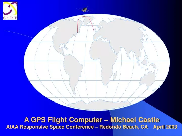
A GPS Flight Computer – Michael Castle AIAA Responsive Space Conference – Redondo Beach, CA April 2003. GPS Flight Computer Overview. GPS Flight Computer concepts SiRFStar2e/LP Block Diagram Flight Computer Concepts SiRFStar2e/LP System overview Flight computer system diagram

E N D
A GPS Flight Computer – Michael CastleAIAA Responsive Space Conference – Redondo Beach, CA April 2003
GPS Flight Computer Overview • GPS Flight Computer concepts • SiRFStar2e/LP Block Diagram • Flight Computer Concepts • SiRFStar2e/LP System overview • Flight computer system diagram • Test Flights • Trajectory Simulation • Sub-orbital Repeater / Imaging application • Applications for GPS flight computer • Future Developments
GPS Flight Computer Concepts • SiRF GPS has enough processor power to act as a flight computer for sounding rockets (50MHz) • Controls vehicle attitude with fins • Logging, Flight Termination and recovery • 1Hz/10Hz update rate requires new type of steering algorithm vs. typical 50Hz rate • Small sounding rockets improved performance from subsonic trajectory and GPS attitude corrections • New applications for sounding rockets • Reduces costs of expendable stages I/O lines SiRF GPS Flight control code Servo Control
SiRFStar2e/LP System Diagram 2Kx32 Cache System Timer 32Kx32 SRAM Bus Interface Unit ARM7TDMI 50MHz ASB 16/32 GPS Engine Track Accelerator WAAS Beacon Battery Backed RAM Bridge Unit UART x 2 SPI port
GPS Flight Computer System Diagram Up to 40 I/O lines Telemetry Transceiver Servo Control SiRF GPS RTC + SRAM Flash Memory +extra RAM Attitude Sensors Serial Port IIC/ADC
Test Flights • Oscillating flight as GPS • updating at 1Hz • Damped oscillations • When launch rail canted • GPS recovers to vertical • Future flights will • improve control loops, • and add mid-flight • corrections
SiRF GPS User Interface simplifies implementation of flight computer • Structured s/w for easy design • User Interface into GPS code, no need to write GPS code etc. • User tasks can be real time, as user can control interrupts, and task scheduling • User task scheduler, 10Hz interrupt rate • Allows easy code migration, multiple tasks running • Ground support code available • 2 UARTs, SPI bus for high speed telemetry • GPIOs to control telemetry/AtoDs/etc • Spare RAM for user code, and a complex lookup tables, matrix manipulation • Guidance Navigation and Control system (GN&C) does not use gyros/accelerometers
Adding a New User Protocol 103 13 /* If GPS is stopped, output no position */ if (LPQueryGPSStopped()) { strcpy(buf,"0,N,0,0,0,0"); umPuts(bufHandle, buf); } /* If GPS is active, get the time and ECEF position and send them out! */ else { CHAR TimeBuff[15], XBuff[15], YBuff[15], ZBuff[15]; /* Note the use of these Module Interface routines to obtain data from */ /* the GPS Core. Check MI_ICD.H for prototype details */ MI_GetTimeGPS (&timegps); MI_GetPositionECEF (&ecef); /* Note that this function is in UI_NMEA.H and we must declare */ /* as an external */ Float2Ascii(timegps.TOW,1,TimeBuff); /* note that Float2Ascii will not handle more than one */ /* decimal point here */ Float2Ascii(ecef.X,1,XBuff); Float2Ascii(ecef.Y,1,YBuff); Float2Ascii(ecef.Z,1,ZBuff); sprintf(buf,"0,Y,%s,%s,%s,%s", TimeBuff, XBuff, YBuff, ZBuff); /* Use the default Put string function to transfer to buffer */ umPuts(bufHandle, buf); } /* Send the whole message, commit to transmit queue */ return (hComm->send (hComm, bufHandle)); } /* OutputUSER1()*/ /* We must register the start/stop characters, and the new message handlers. */ /* Note that we also override the default deliver, send, and allocbuffer */ Attitude Correction code • Attitude Control • If ((VelNed.Vn>1)||(VelNed.Vn<-1) • steern=(VelNed.Vn)*8; //scale to servo range 10-150 • If ((VelNed.Vn>1)||(VelNed.Ve<-1) • steere=(VelNed.Ve)*8; • Provides flight termination capability • drift=(Ltp.Lat-latzone); //0.1 degree lat is 11.1km at 53N • if ((drift>0.1) || (drift<-0.1)) count1s=ALARM; • drift=(Ltp.Lon-lonzone); //0.2 degree lon is 13.2km at 53N • if ((drift>0.2) || (drift<-0.2)) count1s=ALARM;
Trajectory Simulation for GPS Flight Computer • Lightweight top stage completes task • Fire top stage, (possibly separate from fins) • Re-orient for top stage firing, then separate from steering inter-stage coupler • Coast with GPS attitude corrections when subsonic • Separate stages,Recovery of bottom stage • Accelerate to supersonic, stage separation at 50km • Sub-sonic through lower atmosphere to 30km, with GPS attitude corrections • Booster lift-off or air-launched depending on application.
Sub-Orbital Repeater / Imaging beneath cloud cover Application • GPS recovery of lower stages • Top stage flies to destination using GPS at high altitude • Provides high altitude repeater for data • Glide to destination, deploy balloon under clouds and relays images. Glide to destination 1st stage to 60km
Adding a New User Protocol 103 13 /* If GPS is stopped, output no position */ if (LPQueryGPSStopped()) { strcpy(buf,"0,N,0,0,0,0"); umPuts(bufHandle, buf); } /* If GPS is active, get the time and ECEF position and send them out! */ else { CHAR TimeBuff[15], XBuff[15], YBuff[15], ZBuff[15]; /* Note the use of these Module Interface routines to obtain data from */ /* the GPS Core. Check MI_ICD.H for prototype details */ MI_GetTimeGPS (&timegps); MI_GetPositionECEF (&ecef); /* Note that this function is in UI_NMEA.H and we must declare */ /* as an external */ Float2Ascii(timegps.TOW,1,TimeBuff); /* note that Float2Ascii will not handle more than one */ /* decimal point here */ Float2Ascii(ecef.X,1,XBuff); Float2Ascii(ecef.Y,1,YBuff); Float2Ascii(ecef.Z,1,ZBuff); sprintf(buf,"0,Y,%s,%s,%s,%s", TimeBuff, XBuff, YBuff, ZBuff); /* Use the default Put string function to transfer to buffer */ umPuts(bufHandle, buf); } /* Send the whole message, commit to transmit queue */ return (hComm->send (hComm, bufHandle)); } /* OutputUSER1()*/ /* We must register the start/stop characters, and the new message handlers. */ /* Note that we also override the default deliver, send, and allocbuffer */ Sub-Orbital Trajectory
GPS Flight Computer Applications • Sub-orbital applications • Rapid response imaging • Search and Rescue • Atmospheric/Weather research • Research/Educational payloads • Rocket development • Data relay/ bandwidth fill-in • Very low cost (<$1M!) • Proving sub-systems for space Have sounding rockets been forgotten?