Download
1 / 35
360 likes | 480 Views
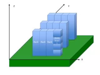
Miniature Modular Rack Launcher Combo. Senior Design Group 3 Casey Brown Cyril John Keith Kirkpatrick Bryan Rickards. Overview. Problem Statement Product Specifications Tigershark UAV Platform Constraints. Concept Generation Latch System Mechanical Safety System Sway Brace

E N D
Miniature Modular Rack Launcher Combo Senior Design Group 3 Casey Brown Cyril John Keith Kirkpatrick Bryan Rickards
Overview • Problem Statement • Product Specifications • Tigershark UAV Platform • Constraints • Concept Generation • Latch System • Mechanical Safety System • Sway Brace • Ejector Mechanism • Conclusion/Next Steps
Problem Statement • Design and develop a Bomb Rack Unit (BRU) that is attached to the Tigershark UAV capable of housing and launching a cylindrical payload. • BRU must contain an electrical interface that allows the user to go through a safety sequence before the payload is released • Provide budget analysis for MMRLC • Prototype and fit check
Tigershark UAV Platform Specifications: • Wing span 21 feet • Propulsion - 372cc two stroke • 20 gallon fuel tank • Empty airframe weight - 150 lbs. • Gross take off weight - 300 lbs. • Payload capacity – 50 lbs. • One hard-point location per wing for launcher attachment
Constraints • BRU must not exceed 5 lbs. • Capable of holding a payload that is 10lbs • Operation in temperature range -20 to 60 degrees C and during rain exposure • Retain payload during aircraft maneuvers up to 2GS lateral load and 1G landing shock.
Latch System • Hold payload in place during aircraft maneuvers • 2Gs lateral load • 1G Landing shock • Integrated with safety system that prevents hooks from opening before “ARM” signal is received. • Integrated into electrical interface allowing the hooks to swing away during the “RELEASE” command
Mechanical Safety System • Moves to allow the hook to open when the system is put in “Armed” mode • Uses a servomotor to achieve this motion Constraints: • Safety pins that mechanically inhibit launching mechanisms during ground procedures • Pins labeled with red “Remove Before Flight” flags • Safety feature that interrupts launch mechanism until “ARM” command is received from the aircraft. • Launcher shall eject payload when “RELEASE” command is received from the aircraft
Design #4 Side view
Design #4 in “Armed” mode Side view
Design #5 Side View
Design #6 Front View
Decision Matrix Designs 2, 5, 6 will be used for the interim design process
Sway Brace • Designed to keep payload stable during air operations • Must be able to withstand aircraft maneuvers up to 2GS lateral load and 1G landing shock • Sway brace may be able to adjust depending on the size/shape of payload • Brace must be easy to use allowing the ground crew easily add and remove payloads.
Ejector Mechanism • Launcher will eject payload when “RELEASE” command is received from the aircraft. • Free fall will not allow enough separation between the wing and payload • Ejection velocity shall be a minimum of 10ft/s • Net ejection energy of no more than 75 ft-lbs
Conclusion/Next Steps • Integration of our components into one cohesive system • Develop a mechatronic system integrated with an intervalometer to organize sequence of events for payload release • Engineering analysis on each component taking into account given constraints • Interim Design