Download
1 / 29
290 likes | 300 Views
A Presentation on ARRESTING MACHINE Vibration IN OLD THERMAL POWER PLANT. DURGAPUR. PRESENTATION BY. Sanat Kumar Gupta DGM (Civil). Priyo Brota Mondal Sr Manager (MTP). SYNOPSIS. Vibration issues at NSPCL Durgapur.

E N D
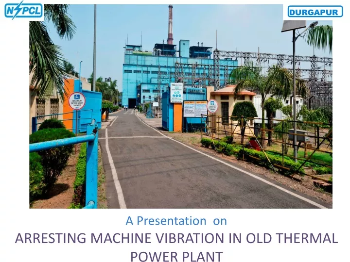
A Presentation onARRESTING MACHINE Vibration IN OLD THERMAL POWER PLANT DURGAPUR
PRESENTATION BY Sanat Kumar Gupta DGM (Civil) Priyo Brota Mondal Sr Manager (MTP)
Vibration issues at NSPCL Durgapur 2x60 MW Captive Power Plant of Durgapur was installed long back in 1985 and is in operation since 1987. Plant has already completed more than 2 lakhs hrs of operation. Due to ageing foundation strength has reduced over the time.
List of rotating machine having vibration issues PA Fans in both unit Seal Air blowers Clinker grinders ID Fan 1/2
ID Fan 1/2 Brief description Each 60MW Unit having two ID fan of 60% Unit capacity ID Fan Specification Capacity-73 m3/Sec, Double suction centrifugal. Operating Speed Range-350-735 rpm Gear Box Ratio-1.84(Input speed 1440-645/output speed 780-350 rpm) Hydro coupling (Fluid coupling)- Input speed-1490r.p.m/ Output speed-1440-645 r.p.m Motor- 550Kw,6.6 KV,1470 RPM Induction Motor
ID fan 1/2 vibration history in chronological order Till 2015 fan runs smoothly afterwards its vibration start increasing gradually. Fan balancing done in opportunity and vibration level reduced. Since September 2017 vibration start raising and balancing failed to reduce vibration. Fan speed restricted to 470 RPM for safe running of fan which impose Unit # 1 load restriction.
Root cause analysis for vibration Detail analysis for vibration reason carried out by Condition monitoring Department. Vibration at Fan bearing mainly NDE side was rising sharply with speed. Vibration observed in entire machine along with base frame and foundation.
Fig showing increasing trend of vibration at Fan NDE(H) side bearing at different time along with displacement.
Observations from vibration data at different speed • Vibration spectral data showed dominant vibration occurring at fan 1x rpm with no significant vibration occurring at any other frequency. • Phase analysis shows in-phase (0°± 30°) motion between horizontal and vertical plane. • Vibration levels in the horizontal direction across the entire machine were much higher than either the vertical & axial directions. • Almost similar vibration amplitude was observed at Fan DE & NDE side base frame and foundation at horizontal directions which is unusual. • Vibration was low (3-4 mm/sec at Fan DE and 4-5 mm/sec at Fan NDE at horizontal directions) up to 460-470 rpm range, but after gradually increasing the speed vibration was dramatically increased & maximum amplitude was found at 558 rpm.
CONCLUSION FROM VIBRATION DATA • Significant vibration felt in the surrounding area (pedestals, foundation & ground) around the fan. • Much higher horizontal versus vertical or axial levels across entire machine. Suspected that foundation strength has been reduced during excavation work for ESP R&M during November 2017. • Dominant 1x with directional vibration at Fan implies resonance or rigidity issue of Foundation and base frame in horizontal direction. • Decision taken to improve structural rigidity, mass addition and rotating assembley replacement during 15 days Unit shut down in April 2019.
Design criteria Nearly all foundations are subjected to either static or dynamic load. One of the criteria of foundation design is based on studying parameters of vibration of a machine at its operating frequency and at its natural frequency. If due to any reason, the operating frequency matches with the natural frequency of the foundation system, vibration will be abruptly high due to resonance ,causing the severe damage to the foundation including the machines.
Our expectations from Machine Foundations Bear Superimposed loads No Settlements Aligned Centre of gravity No Resonance No Unbalanced forces or moments Flexibility to change
How did we arrest the vibration? After various levels of departmental meetings, it was concluded that repair works to be taken along with jacketing of structures with high grade RCC covering minimum 600 mm below ground level.
RESTORATION PLAN Complete restoration plan was divided into following steps Strengthening of the existing pedestal . Increase in the mass of the concrete . Structural connection between new concrete & the old concrete . Replacement of rotating assembly
Strengthening of the existing pedestal Chipping and dismantling of all loose concrete of ID fan main pedestal Application of anticorrosion paint over the exposed reinforcement . Drilling holes of 25 mm in the structure on its vertical face all around and concrete surface was made ready for epoxy grouting. Total 111 holes were made for epoxy grouting with Sikadur 52 and approximately 30 kg of grouting material consumed.
Increase of Mass of Foundation To reduce the vibration, increase of mass is one the techniques by which frequency of the overall structure reduces. Total 35 Cum of high grade RCC (87 ton) was added around the pedestal from 600 mm below ground level.
Connecting New and Old concrete • Both new concrete and the old concrete were structurally connected at reinforcement level to generate monolithic action of the total mass. • Holes were drilled up to 400 mm depth on the vertical face of the pedestal. • 16 mm dia rebars were inserted by Hilti drilling and fixing with RE-500 compound.
Challenges • Operating Plant • Excavation/Dismantling in the vicinity of existing structures • Electric Cables/Trenches/Pipes • Monolithic construction • Potential Hazards • Handling of materials and machinery
Methodology adopted Excavation was carried out by using Jack hammer by dismantling existing concrete and protecting the underground cables and drains. Epoxy grouting was done for strengthening of existing pedestal. PCC was done to lay the reinforcement. Reinforcement of 16 dia tor used horizontally and vertically at the spacing of 200 centre to centre around the pedestal and below ground level in bottom up to 600 mm. M-35 grade concrete was used for concreting work all around the foundation and pedestal. Safe rerouting of cables: C&I cables, Electrical passes for cables and supporting structures for handrail and junction boxes were also rerouted as per the satisfaction of team overhaul.
ISO 10816 A – New machines B – Continuous running without restriction possible C – Not suitable for continuous running, reduced operability until the next scheduled maintenance D – Too high vibration, damage to the machine cannot be excluded