Download
1 / 27
270 likes | 439 Views
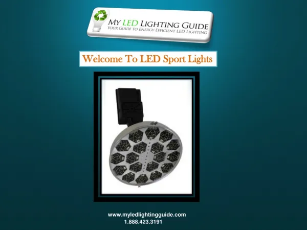
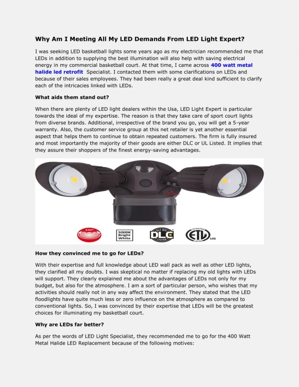
ADAPTIVE LED RING LIGHTS USING PHOTO-DIODE. MINOR PROJECT BY NIDHI SINGH, SHRUTI SINGH & MOHIT HINGORANI DECEMBER 2012 AIT, GURGAON. OBJECTIVE. To create a working model of an intelligent and adaptive lighting system using LEDs to conserve energy.

E N D
ADAPTIVE LED RING LIGHTS USING PHOTO-DIODE MINOR PROJECT BY NIDHI SINGH, SHRUTI SINGH & MOHIT HINGORANI DECEMBER 2012 AIT, GURGAON
OBJECTIVE • To create a working model of an intelligent and adaptive lighting system using LEDs to conserve energy. • At the same time attempt to use a wattmeter and luxmeter to compare the lumens being generated and compare it in live time to standard CFL outputs • In this project we have used a 89s51 controller with an Opamp as a comparator. For light sensing we use LDR as a photosensor. Output of the photosensor is connected to different op-amp and total 8 outputs are taken for reference purpose. These output’s are connected to the microcontroller for comparison. • The microcontroller then controls the number of LED rings being powered up. Hence varying the net intensity of the light installation.
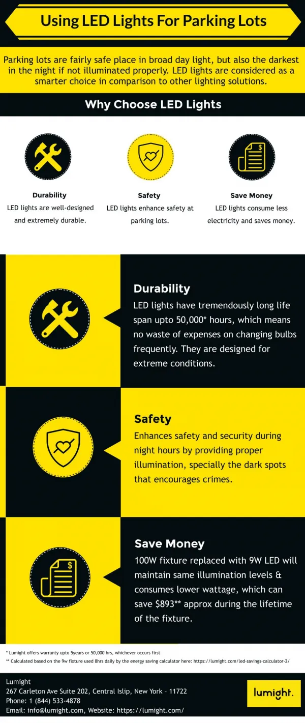
Top 5 ADVANTAGES OF LED Lighting • Beautiful Color • Direction of Light • Long Life • Setting the Mood • Less Power Required
What is the CRI (Color Rendering Index) of the LED light? • What is the CRI (Color Rendering Index) of the LED light? Color Rendering Index is the ability of a light source to reproduce the colors of the object it is illuminating faithfully in comparison with a natural light source. • The CRI is an index from 1 to 100, 100 being a perfect score (e.g. sun light). Those ugly yellow parking lot lights (high pressure sodium lights) have a CRI of 49. The reason we are not a fan of fluorescents are because most of them are in the 60’s and 70’s range and do a poor job of accurately reproducing color. This is especially true in a home where great care was taken in selecting fabrics for furniture, paint color for walls, and floor coverings. • Most LED lights are in the low 80’s. The CREE LED can light has the highest CRI of all the LED can lights produced to date with a CRI of 92.
COMPONENTS USED: 7805 REGULATOR STEP DOWN TRANSFORMER 9-0-9 DIODE IN 4007( 4Pc) NPN TRANSISTOR BC 548 (4) PNP TRANSISTOR BC 558 (4) RELAY 9 VOLT DC (4) ADC 0809 PHOTOCELL MICROCONTROLLER 89S51 LCD 2 BY 16 CRYSTAL 3 MHz RESISTOR 10 K 11 Pc 50 K 2 Pc VARIABLE 470 OHM 1Pc CAPACITOR 22 PF 2 Pc 10 MFD 1 PC 1000 MFD 1 PC
Light Sensors • The light sensor is a passive devices that convert this "light energy" whether visible or in the infrared parts of the spectrum into an electrical signal output. • Light sensors are more commonly known as "Photoelectric Devices" or "Photo Sensors" becuse the convert light energy (photons) into electricity (electrons). • Photoresistors are Semiconductor devices that use light energy to control the flow of electrons, and hence the current flowing through them. The commonly used Photoconductive Cell is called the Light Dependent Resistor or LDR.
Comparator • In this project we use a LM139 as a comparator for room light from window. Lm 139 is comparator IC and there is four comparator is inside the lm 139 • The LM139 series consists of four independent precision voltage comparators with an offset voltage specification as low as 2 mV max for all four comparators. These were designed specifically to operate from a single power supply over a wide range of voltages.
8051 Microcontroller Features • • Compatible with MCS-51™ Products • • 4K Bytes of In-System Reprogrammable Flash Memory • – Endurance: 1,000 Write/Erase Cycles • • Fully Static Operation: 0 Hz to 24 MHz • • Three-Level Program Memory Lock • • 128 x 8-Bit Internal RAM • • 32 Programmable I/O Lines • • Two 16-Bit Timer/Counters • • Six Interrupt Sources • • Programmable Serial Channel • • Low Power Idle and Power Down Modes
LIGHT EMITTING DIODE • Light emitting diode (LED) is a P-N junction semiconductor diode particularly designed to emit visible light. • A normal LED emits at 2.4V and consumes Milliamperes of current. • LEDs often have leads of dissimilar length and the shorter one is the cathode.
Electrical Characteristics Of LEDS • Electrically, a LED is similar to the conventional diode in that it has relatively low forward voltage threshold. Once this is exceeded the junction has a low slope resistance and conducts current readily. An external resistor must limit this current. Forward voltage drew across red LED is nominally 1.6 V but spread with commercial diodes, it may be as high as 2 volts or so, while the Green LED drops 2.4V. This difference accounts for use of lower limiting resistor used with the Green LED. • Another important parameter of the LED is its maximum reverse voltage rating. For typical Red device it is of the order of 3 volts. But for Green LED it is somewhat higher- 5 to 10 volts. • The LED produces light only when a DC current is passed in the forward direction and the amount of light emitted by a LED is proportional to the forward current over a broad range. It means that light intensity increases in an approximately linear manner with increasing current.
LED CONSTRUCTIONS • The first is to ensure that most rays strike the surface at less than the critical angle. This may be achieved by shaping the semiconductor /air interface into a hemisphere. • The second technique is to encapsulate the junction in a transparent medium of high refractive index. This is usually a plastic material with refractive index of about 1.5. Mouldingthe plastic into an approximately hemispherical shape can minimize the losses at the plastic lair interface.
WORKING OF THE PROJECT • The unique aspect of our project lies in the way the LEDs are arranged- • Arranging them in the form of concentric circles ensures that the Light discharged is evenly spread evenly spread out in all directions. • Moreover, when combined with reflecting surfaces, the light will be beautifully spread out and consistent. • The photo sensor senses the ambient light in the room. The analog signal is sent by the sensor to the analog to digital converter, which converts the signal into digital signal, and in this case divided into 4 steps resulting in 4 unique signals. • These signals are sent to the microcontroller via the output lines. • Microcontroller then displays the received data on a LCD screen , where the light output required is displayed. • More importantly, the microcontroller controls the relays that operate the LED rings lights automatically. No human intervention is required during the operation. • Hence, when the ambient light is high, the output of the LEDs is low, and when there is low ambient light, the LED rings light up. • The microprocessor operates at 5V DC and the LED rings also work at 5V DC. • LEDs draw currents in milliamperes. • On the other hand the 5W CFL being operated cannot be dimmed and works at 220V and draws 1.2A of AC current. • However, the Lux output is very similar, which shows that LEDs convert electricity into light energy more efficiently that CFLs. • In this case, the LEDs are approximately 85% more efficient than incandescent bulbs.
WORKING OF THE PROJECT • The microprocessor operates at 5V DC and the LED rings also work at 5V DC. • LEDs draw currents in milliamperes. • On the other hand the 5W CFL being operated cannot be dimmed and works at 220V and draws 1.2A of AC current. • However, the Lux output is very similar, which shows that LEDs convert electricity into light energy more efficiently that CFLs. • In this case, the LEDs are approximately 85% more efficient than incandescent bulbs.