Download
1 / 26
260 likes | 397 Views
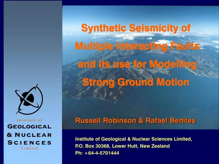
Synthetic Seismicity of Multiple Interacting Faults and its use for Modelling Strong Ground Motion. Institute of Geological & Nuclear Sciences Limited, P.O. Box 30368, Lower Hutt, New Zealand Ph: +64-4-5701444. Russell Robinson & Rafael Benites. h. c. n. e. r. T. c. e. d. a. m.

E N D
Synthetic Seismicity of Multiple Interacting Faults and its use for Modelling Strong Ground Motion Institute of Geological & Nuclear Sciences Limited, P.O. Box 30368, Lower Hutt, New Zealand Ph: +64-4-5701444 Russell Robinson & Rafael Benites
h c n e r T c e d a m r e K h g u o r T i g n a r u k i H t l u a F e n i p l A New Zealandtectonic and bathymetricsetting Image from NIWA National Institute of Water and Atmospheric Research Ltd
Earthquake Commission (EQC) A small fraction of fire insurance premiums is used for earthquake insurance They asked GNS: • What is the probability of two (or more ) large earthquakes in the Wellington region within a few years of one another? • What sort of shaking should we expect from a large earthquake on the Wellington Fault?
Synthetic Seismicity: • Computer model of a network of interacting faults and a driving mechanism. • Generates long catalogues of seismicity so that questions can be answered by statistical analysis. • Computationally efficient but reasonably realistic. • Fault properties are tuned to reproduce known slip rates/directions and other fault properties.
Features: • Coulomb Failure Criterion. • Static/dynamic friction law, modified to include healing. • Okada’s (1992) dislocation routines for calculating induced stresses. • Stress propagation is at the shear wave velocity.
Features: • Induced changes in pore pressure are included. • Mimics dynamic rupture effects to some degree. • All interaction terms are kept in RAM. • The program has been “parallelized” to run on a Beowulf PC cluster.
Wellington Fault Fault Length: 75 km Fault Width: 20 km Fault Dip: 90o Cell Size: 1 x 1 km Coefficient of Friction: Asperity regions: Random between 0.65 and 0.95 Non-Asperity: Random between 0.40 and 0.70 Stress Drop: 25% Static/Dynamic Strength: 0.85 Healing Time: 3.0 s Dynamic Enhancement Factor: 1.2 Pore Pressure: Initially ~ hydrostatic; varies with time Stress Propagation Velocity: 3.0 km/s
Typical ‘Characteristic’ Event Moment: 1.41 x 10²⁰ N-m; Mw 7.40 ModelSommerville (1999) Rupture Area 1500 km2 2810 km2 Average Slip 2.35 m 1.96 m Area of Asperities 345 km2 630 km2 Area of Largest Asperity 272 km2 458 km2 Radius of Largest Asperity ~9 km2 13 km Num. of Asperities 2 + 1 very small 2.6 Area Covered by Asperities 23% 22% Average Asperity Slip 1.67 2.01 Contrast Corner Spatial Wavenumber, Along Strike 0.01 km-1 0.01 km-1 Along Dip 0.01 km-1 0.02 km-1 Slip Duration 3.0 s 2.55 s Rupture Duration ~30 s -
Rupturing ‘snapshots’for a characteristicWellington Fault event
METHOD • Discrete wave number • Generalised reflection/transmission coefficients (Bouchon 1979, Kennet 1973, Chin and Aki 1991) In the plane k-z ky k kx
in which tn is the time shift corresponding to the time step n, XP and XS are the directivity correction factors for P and S waves, respectively, applied to each subfault m, and defined by: with r = average rupture velocity, L = length of the subfault m, and the angle between the point source corresponding to the subfault m and the station. The components of the wavefield contribution of each subfault in the k-z plane are rotated to the geographical coordinates.
The complete wavefield in the source layer L is computed from: for P-SV waves; and for SH waves, where: The propagation through the layers is performed by applying the generalized reflection/transmission coefficients.
Institute of Geological & Nuclear Sciences Limited, P.O. Box 30368, Lower Hutt, New Zealand Ph: +64-4-5701444 www.gns.cri.nz Russell Robinson & Rafael Benites