Download
1 / 38
400 likes | 714 Views
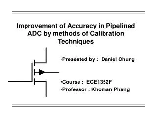
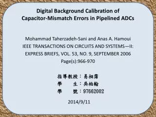
Background calibration techniques for multistage pipelined ADCs with digital redundancy. Outline. Introduction General description Radix-based calibration Background equivalent radix extraction Interference canceling in calibration Simulation results Conclusion. Introduction.

E N D
Background calibration techniques for multistage pipelined ADCs with digital redundancy
Outline • Introduction • General description • Radix-based calibration • Background equivalent radix extraction • Interference canceling in calibration • Simulation results • Conclusion TFE08 Dataconverters / A 14 Bit 1GS/s DAC/ Brillant Grégory
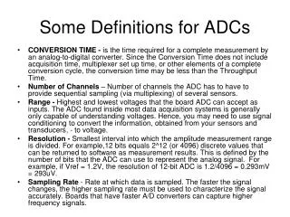
Introduction • This paper proposes a digital background calibration scheme that corrects the linearity errors resulting from capacitors mismatches and finite Opamp gain • Pipelined ADCs are used in high performance digital communication systems • Pipelined ADCs speed can exceeded 100 MSPS • The achievement of more than 12bits resolution generally required linearity enhancement techniques • The use of self calibration techniques is one of the solution TFE08 Dataconverters / A 14 Bit 1GS/s DAC/ Brillant Grégory
General description • In many of self-calibration techniques: • The code errors are calculated in the digital domain • They are subtracted in the analog domain using a separate calibration DAC • But: the subtraction can be made in the digital domain • Low complexity • High accuracy • Avoid foreground interruptions. There are not interruption of the conversion operations to start a calibration cycle TFE08 Dataconverters / A 14 Bit 1GS/s DAC/ Brillant Grégory
General description • An attractive feature of digital self-calibration technique is the minimum extra analog circuit involved • Different background calibration schemes have been proposed: • Resistor string DAC with slow-but-accurate delta-sigma ADC and skip-and-fill algorithm • Bandwidth limitation • Correlation-based methods which use pseudorandom noise sequence • Complex and slow to converge TFE08 Dataconverters / A 14 Bit 1GS/s DAC/ Brillant Grégory
General description • The calibration scheme presented in this paper is a fast and accurate correlation-based background digital calibration scheme for 1.5-bit-per-stage or cyclic ADC • The errors due to capacitor mismatches and finite Opamp gain are corrected by recalculating the digital output based on the equivalent radix of each stage • This technique has a quick convergence if it is used with the two channel ADC proposed in this paper TFE08 Dataconverters / A 14 Bit 1GS/s DAC/ Brillant Grégory
Radix-based calibration • The input signal is quantized by a sub ADC • The output digital code is converted back by a sub DAC • The residue is amplified by two and is used by the next stage TFE08 Dataconverters / A 14 Bit 1GS/s DAC/ Brillant Grégory
Radix-based calibration • Multiplying DAC: sub-DAC, subtraction and amplification are combined together (switched capacitors) • The output of this “capacitor flip-over” MDAC is given by: • D=+/- 1 or 0 depending on the input voltage TFE08 Dataconverters / A 14 Bit 1GS/s DAC/ Brillant Grégory
Radix-based calibration • Non-ideals effect such as capacitor mismatches or gain error add errors to the conversion • The output is given by: TFE08 Dataconverters / A 14 Bit 1GS/s DAC/ Brillant Grégory
Radix-based calibration • The digital output is given by: • Where ra is the modified radix number taking into account the effects of all the error terms. Ra is ideally equal to 2 • Problem: this is false for multistage ADC because the reference voltage will be different from stage to stage TFE08 Dataconverters / A 14 Bit 1GS/s DAC/ Brillant Grégory
Radix-based calibration • Solution: “noncapacitor flip-over” MDAC • Vref and Vi see the same error terms. So, the analog output is: TFE08 Dataconverters / A 14 Bit 1GS/s DAC/ Brillant Grégory
Radix-based calibration • But the radix ra is not the same for each stage! • The correct digital output is given by: • But: the speed of the “capacitor flip-over” MDAC is better than the “noncapacitor flip-over” MDAC • It would be interesting to find a solution which can be applied to both MDAC structures TFE08 Dataconverters / A 14 Bit 1GS/s DAC/ Brillant Grégory
Radix-based calibration • This solution exists, but it required some manipulations • First step: classic pipeline ADC with error terms TFE08 Dataconverters / A 14 Bit 1GS/s DAC/ Brillant Grégory
Radix-based calibration • Second step: • Vref → Vref/2 TFE08 Dataconverters / A 14 Bit 1GS/s DAC/ Brillant Grégory
Radix-based calibration • Third step: • Merging of the gain factor of the reference voltage, the input and the output TFE08 Dataconverters / A 14 Bit 1GS/s DAC/ Brillant Grégory
Radix-based calibration • Fourth step: • Redifinition of the stage input and output TFE08 Dataconverters / A 14 Bit 1GS/s DAC/ Brillant Grégory
Radix-based calibration • The equivalent radix of each stage can be written: • The previous equation for the digital output can be used to calibrate multistage ADCs with “capacitor flip-over” MDAC • This radix-based digital calibration scheme can be applied to any 1-bit-per-stage pipelined or cyclic ADC • It can also be used for 1.5 bit-per-stage with little modifications TFE08 Dataconverters / A 14 Bit 1GS/s DAC/ Brillant Grégory
Background equivalent radix extraction • The correlation-based scheme calibration techniques involve minimum additional analog circuitry • The small error terms are modulated by a pseudo-random sequence in the analog domain • After the conversion, they are detected in the digital domain by correlating the ADC digital output with the same pseudorandom sequence • The combination of the previous radix-based calibration and this correlation algorithm leads to the development of a robust and simple background calibration technique for pipelined ADC TFE08 Dataconverters / A 14 Bit 1GS/s DAC/ Brillant Grégory
Background equivalent radix extraction • PN : +/- 1 pseudorandom noise • PN is scaled by a constant and added to the input of the ADC • It travels trough The inter-stage gain block and it is quantized By the back-end ADC • PN is subtracted in the digital domain • An estimated radix number has to be provided to do this cancellation TFE08 Dataconverters / A 14 Bit 1GS/s DAC/ Brillant Grégory
Background equivalent radix extraction • The digital output is given by: • With: • PN: pseudorandom noise sequence • ra: actual radix • ra/: estimated radix • QN: quantization noise • ON: other noise sources TFE08 Dataconverters / A 14 Bit 1GS/s DAC/ Brillant Grégory
Background equivalent radix extraction • The correlation between the digital output and the pseudorandom noise gives the difference between the actual radix and the estimated one: • PN is uncorrelated to ON or QN. For a long enough pseudorandom sequence, we have: TFE08 Dataconverters / A 14 Bit 1GS/s DAC/ Brillant Grégory
Background equivalent radix extraction • Problems: • The amplitude of the input signal has to be reduced because each stage’s analog output has a maximum full signal range. The adding of the noise can make the output go out the full scale range • It is difficult to inject a very accurately known magnitude noise in tha analog domain TFE08 Dataconverters / A 14 Bit 1GS/s DAC/ Brillant Grégory
Background equivalent radix extraction • The pseudorandom is injected at the input of the sub-ADC instead of the sub-DAC TFE08 Dataconverters / A 14 Bit 1GS/s DAC/ Brillant Grégory
Background equivalent radix extraction • The digital output is: • The correlation gives: • And so: TFE08 Dataconverters / A 14 Bit 1GS/s DAC/ Brillant Grégory
Background equivalent radix extraction • Key point: • The injection of the noise is done at the input of the sub-ADC • It is unnecessary to reduce the signal input magnitude • There is no need of an accurate scaling • The injection of the noise can be done randomly as long as this variation doesn’t exceed the bounds of digital redundancy • Expectation of faster operations and less noise coupling TFE08 Dataconverters / A 14 Bit 1GS/s DAC/ Brillant Grégory
Background equivalent radix extraction • Problems: • Slower and less accurate than the foreground algorithm • During the correlation the input signal is considered as noise and will interfered with the radix error detection making it less accurate and very slow TFE08 Dataconverters / A 14 Bit 1GS/s DAC/ Brillant Grégory
Background equivalent radix extraction • Moreover, the equivalent noise from the input is generally strong regarding the others error terms • This effect limit the calibration accuracy • This problem can be minimized by increasing the length of the pseudorandom sequence • But: the noise level only go down 3dB for each doubling of sequence length TFE08 Dataconverters / A 14 Bit 1GS/s DAC/ Brillant Grégory
Interference canceling in calibration • The precedent problems can be mitigate by the use of a two-channel ADC architecture TFE08 Dataconverters / A 14 Bit 1GS/s DAC/ Brillant Grégory
Interference canceling in calibration • The two ADC channels take the same input, but with opposite polarity • The digital output is: • Two un correlated pseudorandom sequences noise can be used in order to extract the radix of each channel • The ADC’s input signal is cancelled by adding the two output TFE08 Dataconverters / A 14 Bit 1GS/s DAC/ Brillant Grégory
Interference canceling in calibration • If the two ADC channel are perfectly matched, the efficiency of this background calibration can be as good as a foreground algorithm performed in the absence of the input signal • But in the practice, channel mismatches will limit performances • To speed up the radix detection, channel mismatches calibration can be used… TFE08 Dataconverters / A 14 Bit 1GS/s DAC/ Brillant Grégory
Interference canceling in calibration • But?! Two channel means twice more power and area? • Not necessary: • This differential design will not double the size in comparison with a single design with same SNR requirement • The size is dominated by the capacitors area. The capacitors size are determined by the kT/C noise requirement • With the differential design, for the same noise requirement, the size of the capacitor is divided by two • But the number of comparators and digital hardware calibration is doubled TFE08 Dataconverters / A 14 Bit 1GS/s DAC/ Brillant Grégory
Interference canceling in calibration • Proposed ADC in this paper: TFE08 Dataconverters / A 14 Bit 1GS/s DAC/ Brillant Grégory
Interference canceling in calibration • To achieve robust operation, an iterative approach to extract the radix is used. An initial value is given to the estimate value and then the iteration is used to approach the real radix value: • Δis the step size • After a certain number of step, the estimated value converge to the real one • Main advantage: the calibration of each stage is insensitive to the errors of its back-end TFE08 Dataconverters / A 14 Bit 1GS/s DAC/ Brillant Grégory
Simulation results • Behavioral simulations have been performed to verify this calibration scheme • A 17 bit two-stage cyclic ADC is used TFE08 Dataconverters / A 14 Bit 1GS/s DAC/ Brillant Grégory
Simulation results • Gaussian distributed random capacitor mismatches of a σ=0.1% and 60dB Opamp were assumed for this ADC • The same pseudorandom is used for the two channels • The two channels were also given a 1%Vref offset and 1% gain mismatches. • In the radix extraction the number of total samples was 2^20 and the step size Δwas 2^-24 TFE08 Dataconverters / A 14 Bit 1GS/s DAC/ Brillant Grégory
Simulation results TFE08 Dataconverters / A 14 Bit 1GS/s DAC/ Brillant Grégory
Simulation results TFE08 Dataconverters / A 14 Bit 1GS/s DAC/ Brillant Grégory
Conclusion • An accurate calibration can be achieved by recalculating the digital output based on each stage’s equivalent radix • These radices are extracted by using a correlation process with a pseudorandom noise • The inherent digital redundancy allows the compensation of this added noise without reducing the input signal range and without degrading the SNR • The efficiency can be improved by using a two channel ADC TFE08 Dataconverters / A 14 Bit 1GS/s DAC/ Brillant Grégory