Download
1 / 35
350 likes | 501 Views
Maximizing Data Rate of Discrete Multitone Systems Using Time Domain Equalization Design. Milo š Milo š evi ć. Ph.D. Defense. Committee Members Prof. Ross Baldick Prof. Gustavo de Veciana Prof. Brian L. Evans (advisor) Prof. Edward J. Powers Prof. Robert A. van de Geijn. Outline.

E N D
Maximizing Data Rate of Discrete Multitone SystemsUsing Time Domain Equalization Design Miloš Milošević Ph.D. Defense Committee Members Prof. Ross Baldick Prof. Gustavo de Veciana Prof. Brian L. Evans (advisor) Prof. Edward J. Powers Prof. Robert A. van de Geijn
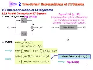
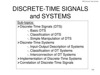
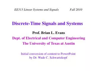
Outline • Broadband access technologies • Background • Multicarrier modulation • Channel and noise • Equalization • Contributions • Model subchannel SNR at multicarrier demodulator output • Data rate optimal filter bank equalizer • Data rate maximization finite impulse response equalizer • Simulation results • Conclusions and future work
Broadband Access Technologies • Wireless Local Area Network • Standardized in 1997 • 15M adaptors sold (2002) • 4.4M access points sold (2002) • Up to 54 Mbps data rate • Data security issues • Cable Network • Video broadcast since 1948 • Data service standardized 1998 • Shared coaxial cable medium: data security is an issue • 42-850 MHz downstream (for broadcast), 5-42 MHz upstream • Data Over Cable Service Interface Specifications 2.0 (2002) • Downstream 6.4 MHz channel: up to 30.72 Mbps (shared) • Upstream 6.4 MHz channel: up to 30.72 Mbps (shared)
Digital Subscriber Line (DSL) Standards • Dedicated link over copper twisted pair • “Last mile” • Widely deployed: North America, West. Europe, South Korea (35M lines) • In US cable leads2 : 1 industry3 : 1 consumer (N.A.) - North America
Wireless Modem Wireless Modem DSL Broadband Access Internet Home Wireless LAN Local Area Network Router Home Hub ATM Switch DSLAM DMT Modem Set-top box downstream Splitter Splitter PC upstream Voice Switch Telephone Customer Premises ATM - Asynchronous Transfer ModeDMT - Discrete MultitoneDSLAM - Digital Subscriber Line Access MultiplexerLAN – Local Area NetworkPSTN - Public Switched Telephone Network PSTN Central Office
Outline • Broadband access technologies • Background • Multicarrier modulation • Channel and noise • Equalization • Contributions • Model subchannel SNR at multicarrier demodulator output • Data rate optimal filter bank equalizer • Data rate maximization finite impulse response equalizer • Simulation results • Conclusions and future work
-fx fx Multicarrier Modulation • Frequency division multiplexing for transmission • Carrier frequencies are spaced in regular increments up to available system bandwidth • Discrete multitone (DMT) modulation • Orthogonal frequency division multiplexing Transmit filter m1 bits Encoding Serial-to-Parallel Converter To physical medium f1 m2 bits M bits Encoding f2 mn bits Encoding Bit rate is M fsymbol bits/s fn
symbol symbol CP CP Discrete Multitone Transmitter Serial-to-Parallel QAM encoder Mirror data and N-IFFT Add Cyclic Prefix Parallel-to-Serial Bits Digital-to-Analog Converter + Transmit Filter 00101 N/2 subchannels(complex-valued) To Physical Medium N coefficients(real-valued) N + n coefficients symbol Q copy 00101 I CP: Cyclic PrefixFFT: Fast Fourier TransformQAM: Quadrature Amplitude Modulation n : cyclic prefix length
Channel and Noise • Channel model • Finite impulse response (FIR) filter • Additive noise sources • Channel noise sources • White noise • Near-end echo • Near-end crosstalk (NEXT) • Intersymbol interference (ISI) • Model other noise not introduced by the channel • Analog-to-digital and digital-to-analog quantization error • Digital noise floor introduced by finite precision arithmetic White Noise, ISI, NEXT, Echo, Quantization Error Output Equalizer Channel Input Digital Noise Floor
Interference • Intersymbol interference (ISI) occurs if channel impulse response longer than cyclic prefix (CP) length + 1 • Received symbol is weighted sum of neighboring symbols • Weights determined by channel impulse response • Causes intercarrier interference • Solution: Use channel shortening filter CP Tx Symbol Tx Symbol Tx Symbol * channel = Rx Symbol Rx Symbol Rx Symbol Tx Symbol Tx Symbol Tx Symbol * channel = * filter Rx Symbol Rx Symbol Rx Symbol
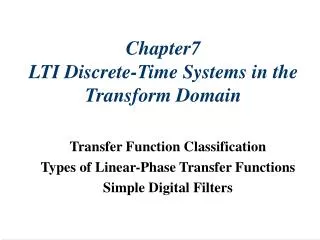
Channel Shortening Filter • Called time-domain equalizer (generally an FIR filter) • If shortened channel length at most cyclic prefix length + 1 • symbol channel FFT(symbol) x FFT(channel) • Division by FFT(channel) can undo linear time-invariant frequency distortion in the channel Channel impulse response Shortened channel impulse response Transmission delay
Discrete Multitone Receiver Frequency domain equalizer = invert channel N-FFT and remove mirrored data Remove Cyclic Prefix Serial-to-Parallel TEQ time domain equalizer Receive Filter+ Analog-to-Digital Converter From Physical Medium N/2 subchannels N coefficients N + n coefficients Parallel-to-Serial QAM decoder Bits 00101
Chow & Cioffi, 1992 Minimum Mean Squared Error Method n • MinimizeE{eTe} Error: e = x*b- y*w Equalized channel: h*w Pick channel delay D and length of b to shorten length of h*w Minimum mean squared error solution satisfies: • Disadvantages Deep notches in shortened channel frequency response Long equalizer reduces bit rate Does not consider bit rate or noise y e x w h + + - b z- Virtual path |DFT{h*w}|
Melsa, Younce & Rohrs, 1996 Channel h (blue line) Yellow – leads to Hwall Gray – leads to Hwin sample number Maximum Shortening SNR Method • Minimize energy leakage outside shortened channel length • Disadvantages • Does not consider bit rateor channel noise • Long equalizer reduces bit rate • Requires generalizedeigenvalue solution orCholesky decomposition • Cannot shape TEQ accordingto frequency domain needs Signal Distortion
Arslan, Kiaei & Evans, 2000 Subchannel SNR Minimum ISI Method • Extends Maximum Shortening SNR method • Adds frequency domain weighting of ISI • Weight according to subchannel SNR; favors high SNR subchannels • Does not minimize ISI in unused subchannels • Minimizes weighted sum of subchannel ISI power under constraint that power of signal is constant qk is kth column vector of N-length Discrete Fourier Transform matrix (*)H is the Hermitian (conjugate transpose) • Method is not optimal as it does not consider system bit rate
Ding, Redfern & Evans, 2002 TEQ 1 FFT Subchannel SNR Comparison FEQ Received Signal TEQ 2 FFT Dual-path Time Domain Equalizer • Received signal passes through two parallel time domain equalizers • One time domain equalizer designed to minimize ISI over the system bandwidth • Other time domain equalizer designed for particular frequency band, e.g. by using Minimum Intersymbol Interference method • Time domain equalizers are designed using sub-optimal methods • FEQ – Frequency domain equalizer
Acker, Leus, Moonen, van der Wiel & Pollet, 2001 yN+M-1 Sliding N-point FFT Z1 0 w1,0 w1,1 wi,M-1 yN+M-2 N/2 Z2 0 N+M-1 w2,0 w2,1 w2,M-1 ZN/2 0 wN/2,0 wN/2,1 wN/2,M-1 y0 Per-tone Equalizer • Transfers time domain equalizer operations to frequency domain • Combined complex multi-tap equalizer • Each tone (subchannel) equalized separately y– received symbol;M – subchannel equalizer length; w – complex equalizer;Zk – received subsymbol in subchannel k; Sliding FFT - efficient implementation of M fast Fourier transforms on M columns of convolution matrix of y with w
Outline • Broadband access technologies • Background • Multicarrier modulation • Channel and noise • Equalization • Contributions • Model subchannel SNR at multicarrier demodulator output • Data rate optimal filter bank equalizer • Data rate maximization finite impulse response equalizer • Simulation results • Conclusions and future work
Contribution #1 Interference-free Symbol at FFT Output • FFT of circular convolution of channel and discrete multitone symbol in kth subchannel is the desired subsymbol in subchannel k at FFT output is desired symbol circular convolution matrix for delay D H is channel convolution matrix qkis kth column vector of N-length FFT matrix • Received subsymbol in kth subchannel after FFT is symbol convolution matrix (includes contributions from previous, current, and next symbol) G(*) is convolution matrix of source of noise or interference Dkis digital noise floor, which is not affected by TEQ
Contribution #1 Model SNR at Output of Demodulator • Proposed subchannel SNR model at demodulator output • Ratio of quadratic functions in equalizer coefficients w • Bits per frame as a nonlinear function of equalizer taps. • Multimodal for more than two-tap w • Nonlinear due to log and flooring operations • Requires integer maximization • Ak and Bk are Hermitian symmetric • Maximizing bint is an unconstrained optimization problem
Contribution #2 Data Rate Optimal Filter Bank • Find optimal time domain equalizer for every subchannel • Generalized eigenvalue problem • Bit rate of bank of optimal time domain equalizer filters
Contribution #2 G0 FEQ0 G1 FEQ1 GN/2-1 FEQN/2-1 Filter Bank Equalizer Architecture y0 Y0 Z0 TEQ Filter Bank Goertzel Filter Bank Frequency Domain Equalizer w0 CP y1 Y1 Z1 CP w1 x Received frame yN/2-1 YN/2-1 ZN/2-1 wN/2-1 CP input TEQ DFT output
Contribution #2 Filter Bank Summary • Advantages • Provides a new achievable upper bound on bit rate performance • Single FIR can only perform at par or worse • Supports different subchannel transmission delays • Can modify frequency and phase offsets in multiple carriers by adapting carrier frequencies of Goertzel filters • Easily accommodates equalization of groups of tones with a common filter with corresponding drop in complexity • Disadvantages - computationally intensive • Requires up to N/2 generalized eigenvalue solutions during transceiver initialization • Requires up to N/2 single FIR and as many Goertzel filters
Contribution #3 Data Rate Maximization Single FIR Design • Find single FIR that performs as well as the filter bank • Maximizing b(w) more tractable than maximizing bint(w) • Maximizer of b(w) may be the maximizer of bint(w) • Conjecture is that it holds true for 2- and 3-tap w • Hope is that it holds for higher dimensions • Maximizing sum of ratios is an open research problem
Contribution #3 Data Rate Maximization Single FIR Design • Gradient-based optimization of b(w) • Find gradient root corresponding to a local maximum • Start with a good initial guess of equalizer taps w • No guarantee of finding global maximum of b(w) • Initial guess: filter bank FIR wkopt resulting in highest b(w) • Parameterize problem to make it easier to find desired root • H(l) is a convex, non-increasing function of vector l • Solution reached when H(l) = 0 • Solution corresponds to local maximum closest to initial point
Equalizer Implementation Complexity • Per tone equalizer and single FIR similar complexity • Filter bank has high complexity • Example shown N = 512 fsymbol = 4 kHz fs=2.208 MHz M = 3 n = 32 fsymbol – Symbol rate fs – Sample rate M – Equalizer length * – Calculations assume N/2 data populated subchannels
Filter Bank Simulation Results • Search to find filter length just before diminishing returns • ADSL parameters except no constraints on bit allocation • ADSL carrier serving area (CSA) lines used • Optimal transmission delay found using line search
Proposed vs. Other Equalization Designs • Percentage of filter bank data rates for same filter length • Each table entry averaged over TEQ lengths 2-32 • ADSL parameters with NEXT modeled as 49 ADSL disturbers LS PTE – Least-squares Per-Tone Equalizer; UEC – Unit energy Constraint; UTC – Unit Tap Constraint
Data Rate vs. Equalizer Filter Length • CSA loop 2 data rates for different equalizer filter lengths • Standard ADSL parameters • NEXT modeled as 49 disturbers expanded
Spectrally Flat Equalizer Response • Some design methods attempt to achieve flatness using empirical design constraints • Example: CSA loop 4 SNR for Single FIR, MBR and Min-ISI • MBR and Min-ISI place nulls in SNR (lowers data rate) • Proposed Single FIR avoids nulls Blue - Single FIR Red – Min-ISI Green - MBR Detail MBR – Maximum Bit Rate Time Domain Equalizer Design
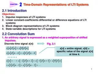
12 - M=3 - M=10 - M=30 10 8 6 Bit Rate (Mbps) 4 2 0 0 10 20 30 40 50 60 70 80 90 100 Transmission Delay Data Rate vs. Transmission Delay • Transmission delay: not known, TEQ design parameter • MMSE: Bit rate does not change smoothly as function of delay • Optimal delay not easily chosen prior to actual design • Exhaustive search of delay values needed • Single FIR: Bit rate changes smoothly as function of delay • Example: CSA loop 1 – “Sweet spot” increases with filter length • Optimal bit rate for range of delays
Conclusions • Subchannel SNR model noise sources not in other methods • Crosstalk and echo • Analog-to-digital conversion noise and digital noise floor • Optimal time domain equalizer filter bank • Bit rate in each subchannel maximized by separate TEQ filter • Provides achievable upper bound on bit rate performance • Available in freely distributable Discrete Multitone Time Domain Equalizer Matlab Toolbox by Embedded Signal Processing Laboratory (http://signal.ece.utexas.edu) • Data maximization single time domain equalizer • Achieves on average 99.3% of optimal filter bank performance • Outperforms state of the art Min-ISI by 2% and MMSE by 15% • Similar performance to least-squares per-tone equalizer
Future Work • Further research into architectures where equalizers are assigned to spectral bands instead for each subchannel • Possibility of integrating time domain equalization with the adjustment of Discrete Fourier Transform carrier frequencies to maximize subchannel SNR • Adaptive and numerically inexpensive implementation of Min-ISI method that removes TEQ length constraint of the original method
Publications in Discrete Multitone • Journal papers • M. Milosevic, L. F. C. Pessoa, B. L. Evans, and R. Baldick, “Optimal time domain equalization design for maximizing data rate of discrete multitone systems,” accepted for publication in IEEE Trans. On Signal Proc. • M. Milosevic, T. Inoue, P. Molnar, and B. L. Evans, “Fast unbiased echo canceller update during ADSL transmission,” to be published in IEEE Trans. on Comm., April 2003. • R. K. Martin, K. Vanbleu, M. Ding, G. Ysebaert, M. Milosevic, B. L. Evans, M. Moonen, and C. R. Johnson, Jr., “Multicarrier Equalization: Unification and Evaluation Part I,” to be submitted to IEEE Trans. On Signal Proc. • R. K. Martin, K. Vanbleu, M. Ding, G. Ysebaert, M. Milosevic, B. L. Evans, M. Moonen, and C. R. Johnson, Jr., “Multicarrier Equalization: Unification and Evaluation Part II,” to be submitted to IEEE Trans. On Signal Proc.
Publications in Discrete Multitone • Conference papers • M. Milosevic, L. F. C. Pessoa, and B. L. Evans, “Simultaneous multichannel time domain equalizer design based on the maximum composite shortening SNR,” in Proc. IEEE Asilomar Conf. on Sig., Sys., and Comp., vol. 2, pp. 1895-1899, Nov. 2002. • M. Milosevic, L. F. C. Pessoa, B. L. Evans, and R. Baldick, “Optimal time domain equalization design for maximizing data rate of discrete multitone systems,” in Proc. IEEE Asilomar Conf. on Sig., Sys., and Comp., vol. 1, pp. 377-382, Nov. 2002.