Download
1 / 53
580 likes | 749 Views
Basic Electrical Systems Theory and Repair. Chapter 29 Page 387. So, Where is Electronics in a Car. Everywhere Antilock brakes, engines, emissions, dash, fuels system, transmissions, tires, suspension, windows, safety systems, lighting. ----Well, I could go on and on and on. The Basics.

E N D
Basic Electrical Systems Theory and Repair Chapter 29 Page 387
So, Where is Electronics in a Car Everywhere • Antilock brakes, engines, emissions, dash, fuels system, transmissions, tires, suspension, windows, safety systems, lighting. • ----Well, I could go on and on and on.
Atoms Positive Negative
Conductors Conductors A good conductor must not have more than four electrons in the outer valence ring of an atom. Copper is one of the best conductors; along with aluminum and gold, conductors have one electron in the outer valence ring.
Insulators Insulators A good insulator must have more than four electrons in the outer valence ring of an atom. Rubber, glass, and porcelain are the best insulators with many electrons in the outer valence ring.
Electron Movement This is the way it really is! Negative to Positive This is what we are taught! Positive to Negative
Wiring is coated with PVC, a flexible plastic to insulate the copper wiring. Color Chart
Load (light) 12 v Complete path Circuit Requirements=A full circle is provided Switch + Source (Battery) _ Source – Battery or voltage supply Load – Electrical components, lights, radio, etc. Complete path for electron flow – Wires and connections
Protection Devices Circuit Devices • Controls Devices Switches for on and off Fuses and Circuit Breakers Protect form Overloads
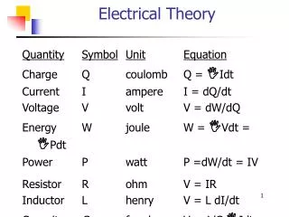
Electrical Terms • Voltage- Also called Electromotive Force, Pressure of electricity or the amount of force it takes to move electrons. Measured in volts. • Current- The movement or flow of electrons, measured in amperes or amps for short. • Resistance-Anything that impedes or slows the flow of electrons. Measured in ohms.
More Electrical Terms • AC – Alternating Current (shop lights and equipment) • DC – Direct Current (Auto battery and most systems) • Auto voltage used is normally between 12 and 15 volts
Circuit Types Series Parallel Combination
12 v Light Series Circuits • Series circuits provide only one path for electron flow through a circuit. • When one component fails, the remaining components quit working. Light Light
Parallel Circuits • Parallel circuits provide two or more paths for electron flow through a circuit. • When one component fails, the remaining components are not affected. Lights 12 v
Combination • The simplest type is to use a switch in the first part of the circuit (series) and the rest of the circuit is wired in parallel. Lights 12 v
Ohm’s Law Greg Simon Ohm (1787 – 1854) Ohm’s Law: It takes one volt to push one ampere of current through one ohm of resistance. *Look at page 394 for more.
E I R Ohm’s Law E = Voltage (Electromotive Force) I = Current (Intensity) R = Resistance (Ohms) E = IR I = E/R R = E\I
E I R 4 ohms 12 volts 3 amps Ohm’s Law E = IR I = E / R R = E \ I E = IR 12 = 3 X 4 I = E / R 3 = 12 / 4 R = E / I 4 = 12 / 3
N N N S S S S N Magnetism Laws of magnetism: 1. Like poles repel each other. 2. Unlike poles attract each other. 3. The attractive force increases as the distance between the magnets decreases.
Magnetism Magnetic Field- Occurs when a current is flowing through a conductor. Electromagnets- Artificially creating a magnetic field. A coil of wire with a voltage applied.
M Electromagnets Switch Battery Starter Solenoid or Relay
A Few More Terms • Semiconductors- Can act as both insulator and conductor. • Diode- an electronic one way check valve, it allows flow one way but doesn’t allow it to reverse the other way. • Transistor- electronic relay. Its very fast, and no moving parts.
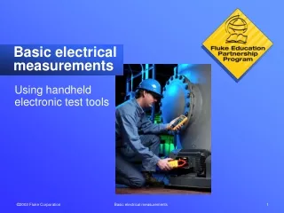
Basic Tests • Meters • Analog and Digital Digital Volt-ohm Meter (DVOM) or Digital Multimeter (DMM)
Testing Voltage After Switch Open = wire broke or fried wire
Circuit Test 3 1 = 12 v 2 = 12v 3 = 12v 1 2 2
Diode Check Diode is a one way street only. Reversing the multimeter leads will tell us if the voltage is allows one way and is stopped the opposite way. If it doesn’t do this toss the diode. .000 one way and 1. the other.
Testing Device with Ohmmeter with Power Removed Continuity Should be .000 if Good Infinity Should be 1. if Bad
Testing Amps Need to change red probe lead to Amp on meter
Using a Jumper Wire Bypassing Ground
Circuit Defects Open Incomplete or broken circuit. The circuits quits working. Short Two wires unintentionally connecting with each other. Could cause more than one component to operate.
Circuit Defects Ground When a positive and negative wire contact each other. Could cause sparking and extreme heat due to high current flow. Very low resistance blows fuses, circuit breakers, or fusible links.
Circuit Defects Open Circuits