Download

1 / 77
800 likes | 1.18k Views
CATALYSIS I . The HYDROFORMYLATION REACTION. THE HYDROFORMYLATION REACTION. Oldest process still in use Responsible for the production of materials from a homogeneous catalyzed reaction 100% atom recovery. THE HYDROFORMYLATION REACTION. O. R. cat. R. +. +. +. H. CO. R. H.

E N D
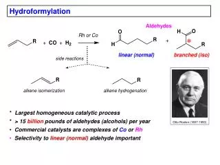
THE HYDROFORMYLATION REACTION • Oldest process still in use • Responsible for the production of materials from a homogeneous catalyzed reaction • 100% atom recovery
THE HYDROFORMYLATION REACTION O R cat R + + + H CO R H 2 H O "iso" "normal" branched product linear product Fig. 7.1. The hydroformylation reaction
HYDROFORMYLATION THERMODYNAMICS H2 + CH3CH=CH2 + CO CH3CH2CH2C(O)H G 63 -138 -117 (l) = -42 kJ.mol-1 H 21 -109 -238 = -150 kJ.mol-1 H2 + CH3CH=CH2 CH3CH2CH3 G 63 -25 = -88 kJ.mol-1 H 21 -105 = -126 kJ.mol-1
COBALT CATALYZED HYDROFORMYLATION REACTION • A prototype homogeneous metal catalysis - precatalyst to an active complex - steps involving organometallic reactions - 16 e to 18 e transition steps - possible geometries of intermediates
STEP a • Formation of the catalytically active species (16 e) from HCo(CO)4 • HCo(CO)4 from Co2(CO)8 + synthesis gas (CO + H2) • Reaction conditions: • (200 – 300 bar, 120-170oC)
STEP a Preferred geometry of the intermediate: (based on calculations)
STEP b binding of the alkene to the active catalyst - forms 18 e complex
STEP b Theoritical calculations indicate a slightly stable 4 (less steric hindrance). Structure 5 has the requisite coplanar geometry for Co, H, and the double bond C atoms)
STEP c 1,2 alky insertion - reversible -elimination is highly possible but high CO partial pressure will stabilize the 18 e- complex
STEP c initial 16e complex 18 e complexes upon CO addition
Step d CO insertion (1,2 alkyl migration)
STEP d 18e 16e
STEPe oxidative addition (H2) – reductive elimination (product) sequence.
8. HydroformylationA comment about metal-ligand ratio Consider the following exercise. The catalytically active complex is involved in the following equilibrium: L + HM(CO) LHM(L) + CO The selective and fast catalyst species we want is HM(L) and we have determined that at a certain pressure we need a twenty-fold excess of L in order to have 95 % of M in the M(L) state. The concentration of M = 10-3 molar. Suppose we want to reduce the concentration of M to 10-5. What should we do with the concentration of L (at constant pressure of CO). What ratio L/M should one choose? What happens if the ratio is kept at 20? (calculate the equilibrium constant from the first example and then calculate the required concentration of L at M = 10-5 molar)
HydroformylationHydroformylation with rhodium phosphite/phosphines
HydroformylationRhodium catalysts for propene Rh/triphenylphosphine: linearity 60 to 96 % Union Carbide Corporation, now Dow Chemicals 30 bar, at 120 °C, at highphosphine concentrations linearity 92%. 300 mol.mol-1(Rh).h-1. Low ligand concentrations, 10-20 mM, 1 mM Rh 10-20 bar and 90 °C low linearities (70%), 5-10,000 mol.mol-1(Rh).h-1.
8.3. Rhodium tpp mechanism, dimers Positive effect of raising H2 pressure
8. HydroformylationKinetics, rate equation, type I equation d'Oro v = k [C3H6]0.54[PPh3]-0.7[Rh]1 (conditions 90-110°C, 1-25 bar CO, 1-45 bar H2, PPh3/Rh ratio 300:1 to 7:1) “type I kinetics”
8. HydroformylationKinetics, rate equation, type II rate equation Garland v = k [RC(O)Rh(CO)4]1[CO]-1.1[H2]1[3,3-DMB]0.1 “type II kinetics”
8. Steric effects for regioselective hf Table 8.1. Hydroformylation of methyl-substituted 1-alkenes Alkene Rate, mol.mol-1.h-1 Linearity, % 1-pentene 11,300 78.4 4-Me-1-pentene 9,300 78.0 4,4-Me2-1-pentene 5,300 85.0 3-Me-1-pentene 9,600 91.0 3,3-Me2-1-pentene 7,600 99.0 Conditions: 90 °C, p(CO/H2) = 20 bar, [Rh]=0.5 mM, [PPh3]=5 mM, [alkene]=0.5 M, initial rates at <20% conversion, no isomerization was observed [18].
8.6. HydroformylationRhodium tppts Ruhrchemie-Rhone Poulenc 1986 Propene and 1-butene Same chemistry as tpp
8.7. HydroformylationSummary of hydroformylation catalysts Catalyst Co Co/phosphine Rh/phosphine Pd/phosphine Pressure, bar 200 70 30 60 Temperature, °C 140 170 120 100 Substrate C3 C3 C3,4 internal C10+ terminal all Product aldehyde alcohol aldehyde aldehyde Linearity, % 60‑70 70‑90 70‑95 70-95 Alkane by‑product, %2 10‑15 0 ? Corrosion + + ‑ ? Metal deposition + + ‑ - Heavy ends + + ‑ ? Catalyst costs (Co=1) 1 10 1000 500
Ligand Bite angle Rate m.m–1.h–1 Ratio l:b 12 126 2550 2.6–4.3 BISBI, 11 113/120 3650 25 13 107 3200 4.4–12 DIOP [also 56] 102 3250 4.0–8.5 dppf [also 33] 99 3800 3.6–5 dppp 91 600 0.8–2.6 dppe 85 2.1 PPh3a 6000 2.4 8.9. Table 8.1. Hydroformylation; Novel bidentates
8. HydroformylationRhodium diphosphine catalysts • BISBI DIOP dppf dppe • Bite angle 113 107 102 99 85 • l/b ratio 66 12 8.5 2.4 • Devon, 1987, Casey, 1992 • 13 4-5 • Consiglio, 1973 Unruh, 1982
8. HydroformylationNovel bidentates 3 Linear/ branched = 10 (patent to Shell, 1987)
Table 8.2. HydroformylationBite angle effects in Xantphos ligands Hydroformylation of octene-1 (1.2 M) X n l/b H, H 102 7 PPh 105 18 SiMe2 109 34 S 111 41 C=CMe2 112 50