Download
1 / 23
280 likes | 642 Views
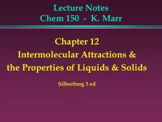
Lecture 13: Phase diagrams 2. PHYS 430/603 material Laszlo Takacs UMBC Department of Physics. Where are we?. Binary phase diagrams tell us what the stable phases are at a given concentration and temperature. Simple but important cases:

E N D
Lecture 13: Phase diagrams 2 PHYS 430/603 material Laszlo Takacs UMBC Department of Physics
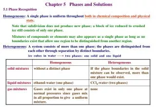
Where are we? • Binary phase diagrams tell us what the stable phases are at a given concentration and temperature. • Simple but important cases: • Ideal solution. Gibbs free energy is dominated by the mixing entropy G = H - TSm Sm = -Nk [c*ln(c) + (1-c)*ln(1-c)] Approximates systems with complete solubility. • Regular solution. Beside mixing entropy, differences in bond energy provide a variation of the enthalpy term G = Hm - TSm Hm = 1/2 Nz [(1-c)HAA + cHBB + 2c(1-c)H0] H0 = HAB - 1/2(HAA + HBB) Can result in limited solubility, if H0 > 0. Read sections 4.1-2, 4.4.3-4, and 9.2.1.2 from Gottstein.
Gibbs’ free energy for a regular solution: • H0 < 0 (strong A-B bonds) makes Gm sharply peaked - ordering, compound formation • H0 > 0 (strong A-A and B-B bonds) can result in two minima. For c1 < c < c2, the lowest energy state is a mixture - phase separation, limited mutual solubility. If HAA = HBB and c << 1, the solubility limit from dG/dc = 0 is c1 = exp(-zH0/kT)
The Au - Pt system: limited solubility in the solid phaseIdentify the liquidus, solidus, and solvus lines. () ()
If the curvatures of the free energy curves for liquid and solid are very different, a minimum or maximum of the liquidus and solidus lines (at the same concentration) can occur.
Follow how the common tangents determine the phase composition
The Au - Cu system. Focus on the liquidus and solidus, the features in the solid phase will be discussed later.
If the two-solid region would extend to above the solidus, a peritectic phase diagram results. Here and may derive from a phase separated solid solution or they can be two unrelated phases with different structures. Cooling across a’a results in a peritectic reaction: L + There are few phase diagrams that show nothing but a peritectic reactions. But peritectic phases are common in more complex phase diagrams.
Gibbs potential curves resulting in a peritectic phase diagram. The minimum of the free energy of the liquid (L) is on the same side of the minima of the free energies for phases and . Notice that the phase compositions are determined by the common tangents of the G(c) curves.
A very rare example. Peritectic reactions are frequent components of complex phase diagrams with many phases, but they rarely occur as the only feature of a phase diagram.
A peritectic reaction dominates the high-temperature part of the phase diagram
Consider a system that has a minimum of the liquidus and solidus curves and also a miscibility gap. (Au-Ni is such a system, see book.) If the two-solid region would extend above the solidus line, an eutectic phase diagram results. At the end, phases and may derive from a phase-separated solid solution or they can be two unrelated phases with different structures. Eutectic phase diagrams are very common, both alone and as part of more complex phase diagrams. At the e’e point the eutectic reaction takes place: L +
The eutectic phase diagram can be related to appropriate Gibbs free energy curves. The minimum of the free energy of the liquid (L) is between the minima of the free energies for phases and .
Two typical eutectic systems: Ag - Cu and Pb - Sn(The latter is complicated by the allotropy of Sn.)
Phase diagram helps understanding the solidification process.
A third phase (a compound, ’) appears. Notice that its presence also restricts the solubility limits, even though the minimum is in between the minima for phases ’ and ’.
Similar to the previous diagram, but the third phase has a broader free-energy minimum and therefore a wider concentration range.
A very sharply defined compound phase. The bond is largely ionic, the compound follows the simple valence rule of chemistry. It also has covalent/ directional character, forms the rather open zinc blende structure. Notice the very high melting point of AlSb compared to both Al or Sb; it suggests a very stable compound, strong bonds. Also notice the eutectic points close to the pure element on both sides.
ZrB2 and ZrC: Line compound versus compound with a broad stability range. ZrB2 has a relatively complex structure with little flexibility. ZrC has the NaCl structure, C is much smaller than Zr. Notice that a few C sites can easily remain unoccupied, but there cannot be extra C in the structure.
Ca and Mg are chemically quite similar. The sharply restricted composition of the CaMg2 phase must be the result of size ratio. This is a Laves phase.