Download
1 / 37
390 likes | 582 Views
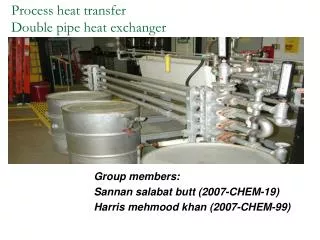
Process heat transfer. Spiral plate heat exchanger. Group members. 2006-chem-01 2006-chem-37 2006-chem-77. construction. Two long strips of plate, which are spaced apart and wound around an open, split center to form a pair of concentric spiral passages.

E N D
Process heat transfer Spiral plate heat exchanger engineering-resource.com
Group members • 2006-chem-01 • 2006-chem-37 • 2006-chem-77 engineering-resource.com
construction • Two long strips of plate, which are spaced apart and wound around an open, split center to form a pair of concentric spiral passages. • Spacing is maintained uniformly along the length of the spiral by spacer studs welded to the plates. engineering-resource.com
Material of construction • Any material that can be cold worked and welded, such as carbon steel, stainless steels, nickel and nickel alloys, aluminum alloys, titanium and copper alloys. engineering-resource.com
Operating conditions • Limitations of material of construction govern design temperature. • Because the turns of the spiral are of relatively large diameter, each turn must contain its design pressure and thickness of plate id somewhat restricted –for these reasons the maximum design pressure is 150 psi. engineering-resource.com
Flow arrangements • Both fluids in spiral flow • One fluid in spiral flow and the other in axial flow • One fluid in spiral flow and the other in a combination of axial and spiral flow engineering-resource.com
Spiral flow in both channels • The spiral assembly includes flat covers at both sides. • The fluids flow counter-currently. • Cold fluid entering at the periphery and flowing toward the core. • Hot fluid entering at the core and flowing toward the periphery. • Can be mounted horizontally or vertically engineering-resource.com
Application • Liquid-liquid service • For gases or condensing vapors if the volumes are not too large engineering-resource.com
Spiral flow in one channel and axial in the other • The spiral assembly contains conical covers, dished heads or extensions with flat covers. • The passage for axial flow is open on both sides and the spiral flow channel is welded on both sides. engineering-resource.com
Application • When there is large difference in volumes of the two liquids • For heating or cooling gases, condensing vapors, or as reboilers. engineering-resource.com
Combination flow • A conical cover distributes the fluid into its passage. • Part of the spiral is closed at the top, and the entering fluid flows only through the center part of the assembly. • A flat cover at the bottom forces the fluid to flow spirally before leaving the exchanger. engineering-resource.com
Application • Often used for condensing vapors. • Vapors first flow axially until their volume is reduced sufficiently for final condensing and sub-cooling in spiral flow. engineering-resource.com
Advantages • Single-flow makes it ideal for cooling and heating sludge and slurries. • Good distribution • Low rate of fouling because of single-flow channel and curved-flow path. • If it fouls it can be easily cleaned. It can be easily cleaned with high pressure water or steam. engineering-resource.com
Continued • Well suited for viscous fluids. • Flow can be assumed completely counter-current , when the fluids are flowing in spirals. No need for correction factor. • In axial flow , a large flow area affords a low pressure drop , which becomes especially important when condensing under vacuum. engineering-resource.com
Limitations • Repairing is difficult. A leak cannot be plugged. However the possibility of leakage is small because of the thickness of the plate. • For spiral-axial flow , the temperature difference must be corrected. engineering-resource.com
“DESIGN STEPS” engineering-resource.com
Steps followed: • Calculation of heat duty • LMTD • Assume any value of design co-efficient • Calculation of heat transfer surface area • Reynold’s number • Selection of type of flow • Selection of equations • Calculation of S.O.P • Pressure drop calculations engineering-resource.com
DESIGNING OF A LIQUID-LIQUID SPIRAL PLATE HEAT EXCHANGER engineering-resource.com
PROBLEM: engineering-resource.com
CONTINUED Material of construction is stainless steel having k=10 For it plate thickness Þ may be taken as 1/8’’, 3/16’’, ¼’’, 5/16’’ • HEAT DUTY: Q=m*Cp*∆T =6225×.71×(200-120) ×1.8 =636400 BTU/hr • LMTD(∆TM): {60-49.4}/ln{60/49.4}=54.5°C engineering-resource.com
FOR FIRST TRIAL: • The approximate surface can be calculated using an assumed overall heat transfer coefficient. U=50 btu/(hr sq. ft. °F) so A=Q/(U*A*∆Tm*1.8) =130 sq. ft. engineering-resource.com
CONTINUED • Because this a small exchanger assume, plate width W=24 in.=2ft therefore L=A/W*2=130/2*2 =32.5ft assume channel spacing=3/8in for both fluids engineering-resource.com
CONTINUED • Reynolds number : NRe=10,000{w/W*µ} Where w=mass flow rate W=channel plate width=24in µ=viscosity engineering-resource.com
Hot side NRe={10,000*6.225}/{24*3.35} =774 Cold side NRe={10,000*5.925}/{24*8} =309 as laminar flow so spiral flow is selected for heat exchanger design engineering-resource.com
HEAT TRANSFER CALCULATIONS • Using eq. 3 hot side: ∆Th/∆Tm=32.6*[M.222/S.889]*[Zf/Zb].14*[w2/3* T2-T1]/∆Tm*ds/LW2/3] =32.6*[200.4.222/.843.889]*[6.2252/3*80/ 54.5]*[.375/242/3*32.5]=0.848 engineering-resource.com
Cold side: ∆Tc / ∆Tm=0.927 FOR FOULING, eq{12}: It is assumed that there is no fouling on hot fluid side. So for cold fluid, ∆Ts/ ∆Tm=6000*[Cp/h]*[w{T2-T1}/ ∆Tm]*1/LW =6000*[.66/1000]*[5.925*90.4/54.5]*[1/32.5*24] =0.050 engineering-resource.com
For plate: ∆Tw/ ∆Tm=500*[Cp/k]*[w*{T2- T1}/ ∆Tm]*[Þ/L*W] =500*[.66/10]*[5.925*90.4]/54.5*[.125/32.5*24]= 0.052 engineering-resource.com
SUM OF PRODUCTS(SOP): • SOP=0.848+0.927+0.050+0.052 =1.877 Because SOP>1, assumed heat exchanger is inadequate . Surface area must be enlarged by increasing L or W. As in all equations L applies directly so new length adopted is 1.877*32.5=61ft. engineering-resource.com
PRESSURE DROP CALCULATIONS: • HOT SIDE (Eq. 15): ∆P = 0.001*(L/s)*[W/(ds*H)]*[1.035*Z0.5/(ds+0.125)]* *[(Zf/Zb)0.17*(H/W)0.5+1.5+16/L] ∆P = [(0.001*61)/0.843]*[6.225/(0.375*24)]* *[{(1.035x3.350.5x1x240.5)/ (0.375+0.125)*6.2250.5} +1.5+16/61] = 0.461 psi COLD SIDE: ∆P = 0.65 psi Because the ∆P is less than allowable, ds can be decreased. engineering-resource.com
SECOND TRIAL: • For 2nd trial, ¼’’ spacing for channels is adopted. • Because the heat transfer Eqn. for every factor except the plate varies directly with ds, a new SOP can be calculated. ∆Th/∆Tm = 0.848*(0.25/0.375) = 0.565 ∆Tc/∆Tm = 0.927*(0.25/0.375) = 0.618 ∆Ts/∆Tm = 0.050 ∆Tw/∆Tm = 0.052 SOP = 0.565+ 0.618+ 0.050+ 0.052 = 1.285 L = 1.285*32.5 = 41.8 ft. A = 41.8 x 2 x 2= 167 sq. ft. engineering-resource.com
NEW PRESSURE DROP IS: HOT SIDE: ∆P = 0.605 psi COLD SIDE: ∆P= 0.861 psi The ∆Ps are less than the maximum allowable. The plate spacing can not be less than ¼’’ for 24’’ plate width; decreasing the plate width would result in a higher than allowable ∆P. Therefore, the design is acceptable. DIAMETER OF THE OUTSIDE SPIRAL: Using the eqn. Ds = [15.36 X L*( dsc + dsh + 2p) + C2]0.5 Ds = [15.36 X 41.8)[0.25+0.25+2(0.125)] + 82]0.5 Ds = 23.4’’ engineering-resource.com
For a spiral plate exchanger, the best design is often that in which The outside diameter approx. equals the plate width. DESIGN SUMMARY: Plate width 24’’ plate length 41.8 ft. channel spacing ¼’’ (both sides) spiral dia 23.4’’ heat trasfer area 167 sq. ft. hot side ∆P 0.607 psi cold side ∆P 0.861 psi U 38.8 Btu/(hr.)(sq.ft.)(F) engineering-resource.com