Download
1 / 30
390 likes | 961 Views
Fluoroscopy. Real-time imaging. Most general-purpose fluoroscopy systems use TV technology, operating at 30 frames/sec May be recorded (barium swallow examinations) or unrecorded (catheter positioning) Cinecardiography may operate at 120 fps using 35mm film

E N D
Real-time imaging • Most general-purpose fluoroscopy systems use TV technology, operating at 30 frames/sec • May be recorded (barium swallow examinations) or unrecorded (catheter positioning) • Cinecardiography may operate at 120 fps using 35mm film • Higher sensitivity than screen-film systems • 1 to 5 R per frame versus 600 R for a 400-speed screen-film system to give OD = 1.0
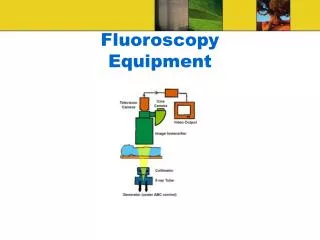
Image intensifier • Four principal components: • A vacuum bottle to keep air out • An input layer to convert the x-ray signal to electrons • Electronic lenses that focus the electrons • An output phosphor that converts the accelerated electrons to visible light
Input screen • Input screen consists of four layers: • The vacuum window (thin Al window that is part of the vacuum bottle) • A support layer (also thin Al), curved for accurate electron focusing • The input phosphor (CsI in thin, needle-like crystals) • The photocathode (a thin layer of antimony and alkali metals, such as Sb2S3) that emits electrons when struck by visible light
Output phosphor • Made from zinc cadmium sulfide doped with silver (ZnCdS:Ag), which emits green light • Small phosphor particles (1 to 2 m) in a thin coating (4 to 8 m) to preserve high spatial resolution • Anode is a very thin (~ 0.2 m) coating of aluminum on the vacuum side of the phosphor
Output phosphor (cont.) • Much smaller image at the output phosphor than at the input phosphor (23- to 35-cm diameter input imaged focused onto a 2.5-cm diameter circle) • Must deliver resolution >70 line pairs/mm to preserve a resolution of 5 line pairs/mm at the input plane
Quantum detection efficiency • X-rays must pass through the vacuum window and the input screen substrate before reaching the phosphor • This reduces the QDE of an image intensifier • Maximal around 60 kVp • Dose to patient decreases at higher kVps, so optimal kVp for a given examination will generally be higher than 60 kVp
Modes of operation • Continuous fluoroscopy • Basic form of fluoroscopy; continuously on x-ray beam • High dose rate fluoroscopy • Specially activated mode allowing exposure rates of up to 20 R/min to the patient in the US • Variable frame rate pulsed fluoroscopy • 30, 15, and 7.5 frames/sec operation allows lower temporal resolution for parts of procedure • Frame averaging
Frame averaging • Fluoroscopy images generally noisy • Sometimes beneficial to compromise temporal resolution for lower noise images • Digitize fluoroscopic images and perform real-time averaging in computer memory for display
Automatic brightness control • Purpose of ABC is to keep brightness of the image constant at the monitor • Accomplished by regulating the x-ray exposure rate incident on the input phosphor of the II • As II pans from a thin to a thick region of the patient, thicker region attenuates more of the x-rays • Video signal itself can be used to sense light output • ABC can adjust both tube current and generator voltage
Image quality • Spatial resolution of the II best described by modulation transfer function (MTF) • The limiting resolution of an imaging system is where the MTF approaches zero • Higher magnification modes (smaller fields of view) are capable of better resolution • Video imaging system degrades the MTF substantially
Image quality (cont.) • Contrast resolution of fluoroscopy is low compared with radiography because low exposure levels produce images with relatively low signal-to-noise ratio (SNR) • Excellent temporal resolution of fluoroscopy is its strength and its reason for existence
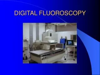
Fluoroscopy suites • Smaller facilities may use one fluoroscopic system for a wide variety of procedures • Larger facilities have several suites dedicated to specific applications, such as: • Gastrointestinal suites • Remote fluoroscopy rooms • Peripheral angiography suites • Cardiology catheterization suites • Biplane angiography systems • Mobile fluoroscopy – C arms
Radiation dose • Maximum entrance exposure rate for fluoroscopy to the patient is 10 R/min (see http://www.hc-sc.gc.ca/hecs-sesc/ccrpb/publication/safety_code20a/toc.htm) • Low-dose techniques include heavy x-ray beam filtration, use of low frame rate pulsed fluoroscopy, and use of lower-dose ABC options • Last-frame-hold features often reduce fluoroscopy time • Using the largest field of view suitable to a given clinical study also helps reduce radiation dose to the patient
Dose to personnel • Occupational exposure of physicians, nurses, technologists, and other personnel who routinely work in fluoroscopic suites can be high • Lead aprons should be worn when the x-ray beam is on • Portable lead glass shields should be available for additional protection to staff members observing or otherwise participating in the procedure • Reducing total fluoroscopy time is beneficial to everyone