Download
1 / 18
180 likes | 183 Views
This document discusses the results of the beam line commissioning phase in 2004, implications and tests for phase 2 in 2005, and the status of new components such as the separator, beam transport solenoid (BTS), and vacuum system. It also includes information on the cryogenic transfer lines, He-bag/target, and the schedule for 2005.

E N D
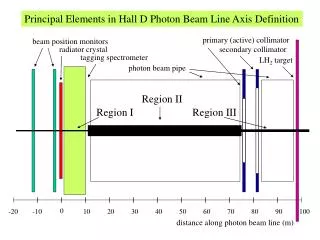
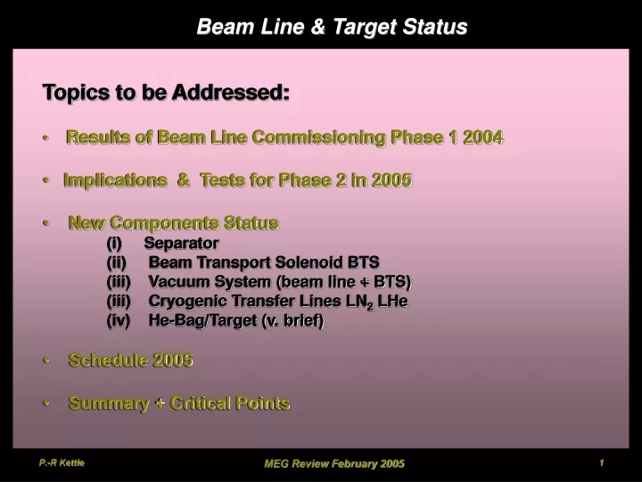
Beam Line & Target Status • Topics to be Addressed: • Results of Beam Line Commissioning Phase 1 2004 • Implications & Tests for Phase 2 in 2005 • New Components Status • (i) Separator • (ii) Beam Transport Solenoid BTS • (iii) Vacuum System (beam line + BTS) • (iii) Cryogenic Transfer Lines LN2 LHe • (iv) He-Bag/Target (v. brief) • Schedule 2005 • Summary + Critical Points MEG Review February 2005
Trip I Trip II COBRA ASC Sep Y X BTS Beam Line Commissioning 2004 Phase 1 • Phase 1: June – August 2004 • Reason for More beam tuning: • new Triplet I QSBs (before QSMs LEMS)- optical + physical properties different • old Separator (equivalent to new Separator) – electrostatic + physical properties similar, • magnetic properties different • new Triplet II QSKs - optical + physical properties different • optics Triplet I BTS non-trivial dispersion, double-waist, vertically parallel • finalize optics up to injection BTS try to reduce divergence & • hence influence on beam-spot size in COBRA MEG Review February 2005
Trip. Colli. WIEN Solenoid µ+ µ+ Triplet 2 e+ e+ Filter 1 Beam Line Commissioning Results Phase A Momentum-Spectrum: Data: whole Beam Line optimized for each data point + 2-D Scan for each point !!! Theory: -Kinematic Edge (29.79 MeV/c) Theoretical func. P3.5 folded with Gaussian ΔP/P + Const. Cloud µ+ contribution Fitted to data Integrated μ+ Rate 4cm Tg.E @ 1.8mA Rµ~1.26·108 µ+/s (2.3·108 µ+/s 6cm Tg.) Integrated e+ Rate 4cm Tg.E @ 1.8mA Re~7.7·108 e+/s e+/μ+~ 6.1 2/dof = 0.94 Pcent = (28.16 0.02) MeV/c P/P = (7.7 0.3) % FWHM Pbeam = (28.2 0.9) MeV/c MEG Review February 2005
Beam Line Commissioning Results Phase A –cont. Provisional Results -Integral Spot Rates MHz for 1,8mA Proton Current & 4cm Target E Normalized to Momentum Slit Settings: FS41L/R 250/280 FS43L/R 240/220 • First - Beam Studies with MEG Beam: • for calibration purposes in the experiment • -p→0n, -p→n • 55 → 83 MeV s and 129 MeV s • Data taken from: • P-spectrum measurements 25-33 MeV/c • s detected above 30 MeV/c (pulse-ht. + RF tof) • dedicated - runs at 56 MeV/c & 103 MeV/c • 56 MeV/c interesting since max. momentum • that can be transported to COBRA with • good optics SNM in BTS • dedicated CEX run at 112 MeV/c e- μ- 56 MeV/c R = 7.6 ·106 -/s slits open R = 7.2 ·105 -/s slits70/70 - MEG Review February 2005
Trip. Colli. WIEN Solenoid µ+ µ+ Triplet 2 e+ e+ Filter 1 Beam Line Commissioning Results Phase B Divergence Fits Separator -195kV • Optimization (Triplet I, Separator, Triplet II) - not so straight forward • extensive beam divergence studies done over > 1m in vacuum 3 tunes studied Optimal Rate Optimal Separation Optimal Rate + Separation Minimal Divergence Dispersion Beam Profile entrance BTS Sep = OFFRμ= 1.11·108 μ+/sat 1.8 mA, 4cm TgE Sep=-195kVRμ= 1.09·108 μ+/sat 1.8 mA, 4cm TgE X~ 17.6 mm y~ 15.8 mm Separation e-μ ~7.5 121 mm physically Transmission Factor (TII-> BTS) TSEP195= 86.5% !!! Hyperbolic Fit Ax2+y2+Bxy=n2 X-Waist 805mm DS TIIx’= 10 mrad (fac5) Y-Waist 735 mm DS TII y’= 15 mrad (fac1.5) Mean Collimator position 760 mm DS TII MEG Review February 2005
Beam Line Commissioning Results Phase B –cont. • Conclusions: • Transmission factor 86.5 % achieved • Better Separation 7.5 , 121 mm • Dispersion minimized up to entrance BTS • Divergences reduced factor ~ 5 in x’ factor 1.5 in y’ Simulation with Geant must Confirm COBRA Spot-size first before freezing design Proposed Layout TripletII BTS (allows all tune modes) MEG Review February 2005
r y z x 8mm dia. Implications Phase 2 Commissioning Phase 2 Commissioning involves BTS + COBRA – High Rate & High Magnetic Field !!! • Present method – won’t work • 2-D Scanner • Hamamatsu PMT R7400U • 2mm pill scintillator • or 60cm Fibre-pill • New Approach needed – COBRA • 3-D COBRA Magnet Measuring Machine • APD • 2mm pill scintillator • He Bag • Hamamatsu R7400U • PMT • 8 stage • active dia. 8mm • 300-650nm • max420nm (Blue) • Sadygov-JINR • APD • micro-pixellated • Geiger-mode G~30k • 2.7x2.7 mm2 act. • 20k pixels/mm2 • 1 pix. 7μ x7μ • 350-750nm • max400nm (Blue) “Golovin” type- green sens. Gain 106 30μ x 20μ MEG Review February 2005
APD Beam Test – LEMs Beam (μE4) Dec. 2004 Goal: Confirm that beam phase space measurements with APD PMT measurements under “real” conditions APD 2 mm Pill PMT 2 mm Pill 8.5 mm Pill Slow Charge-sensitive Preamp use TFA e+ e+ µ+ APD µ+ Surface Muon Beam Signal RF With 2mm CH2 Plate - only e+ e+ • APD/PMT sensitivity approx. same • APD e+ sensitivity worse noise higher • Solution: • Peltier Element (cooling) • green sens. APD + Bicron scint. APD No CH2 Th. 310mV only μ+ some Landau e+ Fourier Power Spectrum Low freq. + 50 MHz RF µ+ MEG Review February 2005
APD Beam Test – LEMs Beam (μE4) Dec. 2004 – cont. PMT 2 mm Pill APD 2 mm Pill PMT 8.5 mm Pill Distance z ~ z0-26mm Rate(µ+) = 9.4 M/mAs X= 13.1 mm Y= 14.8 mm Distance z ~ z0+18mm Rate(µ+) = 9.9 M/mAs X= 15.0 mm Y= 16.4 mm Distance z ~ z0mm Rate(µ+) = 10.6 M/mAs X= 13.8 mm Y= 15.7 mm • Conclusions • Method works – improvement to noise needed for e+ • Rates compatible within beam/target variations ~ 5-10% • Profiles compatible when corrected for Mult. Scatt. • separately tested up to B = 8T MEG Review February 2005
New Components Status: Separator • MEG design finished end Oct. • all parts ordered or being manufactured • 200 kV HV power supply delivered • magnet parts ordered delivery end Dec. • magnet power supply available • magnet power cables laying shutdown • Time scale: • Assembled + Tested ~ Beg. May 2005 Beam 2 5 7 9 m m Beam Upstream Side 1885mm Properties Vmax 200kV Dplates 19cm Leff 70cm 2371 mm MEG Review February 2005
New Components Status: BTS • 6 Main Components (supply) • Cryostat + Coils (BINP) • Cryo-Connector Chamber (BINP) • Valve Chamber (PSI) • Support Stand (BINP) • Power Supply (PSI) • Cryogenic Transfer Lines (PSI) • Vac. & Window Flanges (PSI) 2810 mm 2630 mm 380 mm 460 mm 300 mm Time Scale Materials procurement July 2004 Purchase Order end July 2004 Contract Signed beg. Aug. 2004 Design Approval (PSI) Nov. 2004 Production complete: (Large Parts) *end Feb. 2005 (Small Parts) end Jan. 2005 Assembly BINP *Feb.-Mar. 2005 Performance Tests BINP *April 2005 Delivery PSI (week 20) *mid May 2005 Installation+ Acceptance Tests (6 weeks) *end June 2005 Main Specifications LCryo 2810 mm DBore 380 mm DCoil 460 mm LCoil 2630 mm BMax <0.5 T Imax 300 amps LMax 0.98 H EStored 44 kJ • Outstanding: • vac. + window flanges –Drawing Office • Power Supply: – ordered delivery Mid-April 2005 • Control System – under design MEG Review February 2005
New Components Status: BTS – cont. Cryo-Connector Chamber Current lead BTS Cryostat + Cryo-Connector Chamber Contains cryo Connections for main Cryostat Dewar i/P LHe i/p LHe o/p Valve Chamber connects to LHe transfer Line contains Joule-Thompson Valves for control MEG Review February 2005
New Components Status: BTS – cont. • Updated BTS Production Schedule • cryostat cylinders – formed, machining still necessary • large cryostat end-flanges - made, final machining necessary • tower flanges + internal parts – finished, assembly in progress • coil-support structure – ready for fibre-glassing + epoxying & bending • coil manufactured – ready for forming Delay 3-4 weeks expected compared with original schedule • ~ 50% delay non-technical nature – 1St time Russia has 2 weeks extra Christmas Holidays i.e. workshops closed ~ 50% delay technical nature delay coil support Structure – too long !!! 1:1 tower drawing on door MEG Review February 2005
Pump 1 3μ Diff. window Mylar Window Pump Sep X SEP BTS Trip I Trip II wall X X X Beam Vac X BTS Isolation Vac Pump 2 Pump 3 Vacuum System Beam Line + BTS • Pump Stands needed • Beam Line: downstream of Triplet II • BTS Isolation vacuum up to interface • LHe Transfer Line 4 Gauss 9 Gauss 9 Gauss 30 Gauss • Problem: high Bfield environment ~200 G • Max allowed B~ 4mT (40G) • Combined Solution found Pump stand 3 • Stray B ~2030G • Components ordered • control system under design B T S B T S ~200G ~60G MEG Review February 2005
Cryogenic Transfer Lines • LN2 –Transfer Line: • Order placed • delivery end Jan.2005 • being installed NOW !!! • available ~mid Feb. 2005 to E3 EH LHe BTS LN2 BTS • LHe–Transfer Line: • Order placed • delivery mid March 2005 • available beg April 2005 LN2 Calo From μE4 LN2 LHe LHe Transfer Line MEG Review February 2005
12% He loss 3% Decays Transmission Profile (no Target) Degrader No loss He Bag/Target System • Final Layout He Bag System • Dimensions cannot be frozen • until Geant simulation with • final beam optics confirms • beam phase space in COBRA • He bag required between BTS • window & COBRA cryostat • Advantageous to fill COBRA • completely with He • i.e. “COBRA-Bag” • e.g. Minimize Mult.Scattering • Maximize X0 • He/Vacuum interface Problematic • - Material/leakage • Position determined by – optics, • degrader thickness - being finalized • Target System • Serious work will start when optics Frozen • i.e. post Geant simulation of final optics • simulation of non-stopped μ+ as well as Michels • will also be done as He ½ target thickness • therefore μ+ which miss Tgwill stop at downstream • side of detector MEG Review February 2005
Schedule 2005 • Changes 2005: (compared to previous schedule) • Shutdown only 3 months • BTS Schedule + 6 weeks • target design + manufacture extended • Separator delay + 1month • shift of Gotta et al. by 4 weeks??? MEG Review February 2005
Summary Points • Beam Line / Detector Design: • Extensive Beam test made during Commissioning 2004 – • excellent transmission intensity • good separation quality • several optics studied • Study of - beam for detector calibration done • Beam Line component design BTS, Separator finalized & under construction • Beam line infrastructure LN2, LHe transfer lines, vacuum systems • designs finished & ordered + installation started • Final GEANT simulation of the optimized optics underway to • define FINAL LAYOUT incl. Platform/COBRA • He-Bag System design discussions underway “COBRA-BAG” • Now have PSI Design Engineer for • Target / He-bag System as well as Beam Line components • Critical Paths for Detector Time Schedule 2005: • BTS delivery Mid May 2005 • Separator completion Beg. May 2005 • BTS Power Supply delivery April 2005 • He-Bag for beam measurements MEG Review February 2005