Download
1 / 24
240 likes | 249 Views
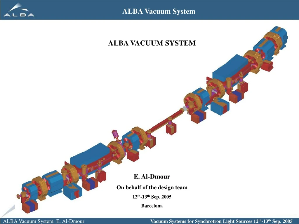
ALBA VACUUM SYSTEM E. Al-Dmour On behalf of the design team 12 th -13 th Sep. 2005 Barcelona. Talk Outline General layout of the machine. The vacuum system layout. Deformation calculations. Power calculations. Absorbers design. Pumping speed and pressure profile. Instrumentations.

E N D
ALBA VACUUM SYSTEM E. Al-Dmour On behalf of the design team 12th-13th Sep. 2005 Barcelona
Talk Outline • General layout of the machine. • The vacuum system layout. • Deformation calculations. • Power calculations. • Absorbers design. • Pumping speed and pressure profile. • Instrumentations.
General Layout of the machine. * 4 fold symmetry. * 8 unit cells * 8 (Matching+ inv. Matching cells). * Straights: 4 LSS (8m): one for injection straight+ 3 for ID. 12 MSS (4.2m): All for ID. 8 SSS (2.6m): 3 for RF cavities, 2 for Diagnostics, the 3rd harmonic cavity, 2 IDs.
General Layout of the machine. Main parameters Unit Cell Matching Cell Inverse Matching Cell
Unit Cell The Vacuum system layout • Stainless steel chamber. Copper/Glidcop absorbers. • Antechamber. • Lumped absorbers, no distributed absorbers except for the dipole vacuum chamber.
Matching Cell Inverse Matching Cell The Vacuum system layout
The vacuum system layout Dipole vacuum chamber 150l/s 300l/s 1. Standard dipole vacuum chamber. 2.Cooling coils/ cooling channels.. 3. Two absorbers. 4. Tapering to follow the Dipole magnet profile.
The Vacuum system layout Post-Dipole vacuum chamber BMbeam line 500l/s ID beam line 300l/s Block 2b • Two absorbers, two pumps (500l/s, 300l/s) • Two pipes for the ID and BM beam line.
NEG pumps 150l/s The Vacuum system layout Pre-Dipole vacuum chamber Block 1b Minimum clearance between the magnets and the vacuum chamber is 2.0mm.
The Vacuum system layout The straights vacuum chamber 150l/s MSS 150l/s 1. Generic vacuum chamber for the straights which are not going to use in day one for IDs and for commissioning. 2. one absorber by the end of the straight. 150l/s
Deformation calculations Deformation for the critical vacuum chamber (largest width, longest distance between BPM). Max. deformation under vacuum=0.52mm
The Surface power density and the foot print of the power in the absorber. normal incidence Power calculations Total power from bending magnets = 407.0 kW Maximum Linear power density = 64.4 W/mm. Maximum Angular Power Density = 249.5 W/mrad2. Maximum Surface power density = 246.2 W/mm2. Maximum total power on the absorbers = 6.7 W Minimum distance from source point to the absorbers = 1.0 m • The effective vertical angle is 0.25 mrad, Surface power densities with respect to the angle of incidence.
Absorbers design. The absorber of Soleil has similar load conditions like ALBA.
Absorbers design. *Most of the radiation is absorbed by row A and B. *Row C is for the reflected photons and from the rest of SR which pass after row A and B.
Absorbers design. Input power values were with normal incidence and the effective vertical angle of the footprint was considered on the inclined teeth. The max. cooling channel temp.=71˚C and unifrom for the 5 pin-holes.
Pumping Speed LSS MSS SSS * Nominal pumping for a vacuum cell= 3250 l/s * Nominal pumping speed for the storage ring= 57,400 l/s (from SIP) * Effective pumping speed for the storage ring=35,850
Pressure Profile Monte-Carlo simulations by Molflow, for 50m of the storage ring First injection: 3GeV, 10mA ηPSD = 2.0∙10-3 molec/ph. Total Pressure= 5.23∙10-8mbar Thermal desorption = 1∙10-11 mbar.l/sec.cm2 Base Pressure= 7.2∙10-10 mbar
Pressure Profile First injection: 3 GeV, 500 Ah, nominal current=250mA Total Pressure= 2.0∙10-9mbar
Pressure Profile Fully conditioned vacuum chamber: 3 GeV, 1000 Ah, maximum current=400mA Total Pressure= 1.77∙10-9mbar
PSD yield* Pressure Profile The effect of an in –situ bake out on the average pressure * The report of the design specifications of Diamond synchrotron light source. June 2002. …. and the pressure on the beam lifetime
Acknowledgements L. Schulz, R. Kersevan, E. Huttel and C. Herbeaux. Engineering Division members who contributed to this work: M. Quispe, B. Calcagno, L. Ribó, and R. Martin