Download
1 / 29
290 likes | 385 Views
Computer Views. Computer Architecture CS 215. Some terms. K (kilo) = 2 10 = 1,024 M (mega) = 2 20 = 1,048,576 G (giga) = 2 30 = 1,073,741,824 T (tera) = 2 40 = ???. Viewpoints. User Programmer Architect Logic Designer. User’s View. Often called end-user

E N D
Computer Views Computer ArchitectureCS 215
Some terms • K (kilo) = 210 = 1,024 • M (mega) = 220 = 1,048,576 • G (giga) = 230 = 1,073,741,824 • T (tera) = 240 = ???
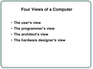
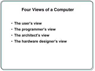
Viewpoints • User • Programmer • Architect • Logic Designer
User’s View • Often called end-user • Does not see implementation, only end results
Programmer’s View • Functional behavior of a computer as viewed by a programmer • Instruction Set Architecture (ISA) • Functional units • Data type sizes, operations, etc.
Instruction Classes • Data movement • Arithmetic/Logic • Control flow
More terms • Machine state • Contents of all registers and machine memory • Procedure calls • Used to implement functions • Machine interrupts • Unexpected interruptions to normal execution • Exceptions • Internal problems with normal execution
Architect’s View • Structural relationships that are not visible to the programmer • Driven by performance needs & csot constraints • Interfaces, clock frequency, memory, etc.
Logic Designer’s View • Works in both Boolean logic and implementation • Concerned with … • Design correctness • Constraints • Ex. Fan-in and Fan-out • Uses various design and analysis tools
Von Neumann Model Memory Unit • Input Unit • Provides instructions and data to system Input Unit Arithemtic and Logical Unit (ALU) Output Unit Control Unit
Von Neumann Model Memory Unit • Output Unit • Returns data from system Input Unit Arithemtic and Logical Unit (ALU) Output Unit Control Unit
Von Neumann Model Memory Unit • Memory • Storage for instructions and data Input Unit Arithemtic and Logical Unit (ALU) Output Unit Control Unit
Von Neumann Model Memory Unit • ALU • Processes data Input Unit Arithemtic and Logical Unit (ALU) Output Unit Control Unit
Von Neumann Model Memory Unit • Control Unit • Directs processing Input Unit Arithemtic and Logical Unit (ALU) Output Unit Control Unit
Von Neumann Model Memory Unit • CPU • ALU and Control Unit combined CPU Input Unit Arithemtic and Logical Unit (ALU) Output Unit Control Unit
System Bus Model • Streamlined version of von Nuemann model • Data Bus • Address Bus • Control Bus • Power Bus (optional) CPU (ALU, Registers, & Control) Memory Input & Output (I/O) Data Bus Address Bus System Bus Control Bus
System Bus Model • Data Bus • Carries the information being transmitted • Sometimes implemented as data-in and data-out buses CPU (ALU, Registers, & Control) Memory Input & Output (I/O) Data Bus Address Bus System Bus Control Bus
System Bus Model • Address Bus • Identifies where the information is being sent • “Memory” address identifies read/write location CPU (ALU, Registers, & Control) Memory Input & Output (I/O) Data Bus Address Bus System Bus Control Bus
System Bus Model • Control Bus • Describes aspects of how the information is being sent, & in what manner CPU (ALU, Registers, & Control) Memory Input & Output (I/O) Data Bus Address Bus System Bus Control Bus
Machine Levels User or Application Program Level • Each level represents an abstraction of the computer • Levels are kept relatively independent from one another • Can allow for upward compatibility High-Level Language Level Assembly Language / Machine Code Level Control Level Functional Unit Level Logic Gates Transistors & Wires
User or Application Program Level User or Application Program Level • User interacts with computer High-Level Language Level Assembly Language / Machine Code Level Control Level Functional Unit Level Logic Gates Transistors & Wires
High-Level Language Level User or Application Program Level • Compiler maps data types and instructions to actual computer hardware • Can be recompiled in different environments • Source code compatibility High-Level Language Level Assembly Language / Machine Code Level Control Level Functional Unit Level Logic Gates Transistors & Wires
Assembly Language / Machine Code Level User or Application Program Level • Language of the computer • Instruction sets • Assembler substitutes instruction codes for mnemonics • Different hardware can support same instruction set High-Level Language Level Assembly Language / Machine Code Level Control Level Functional Unit Level Logic Gates Transistors & Wires
Control Level User or Application Program Level • Effects register transfers • Control signals transfer data from register to register • Hardwired Vs. Microprogram control • firmware • microcontroller High-Level Language Level Assembly Language / Machine Code Level Control Level Functional Unit Level Logic Gates Transistors & Wires
Functional Unit Level User or Application Program Level • Internal CPU registers • ALU • Computer’s main memory High-Level Language Level Assembly Language / Machine Code Level Control Level Functional Unit Level Logic Gates Transistors & Wires
Logic Gates, Transistors & Wires User or Application Program Level • The hardware! • (More on this later) High-Level Language Level Assembly Language / Machine Code Level Control Level Functional Unit Level Logic Gates Transistors & Wires
Question? User or Application Program Level • Which levels map to which views? High-Level Language Level Assembly Language / Machine Code Level Control Level Functional Unit Level Logic Gates Transistors & Wires
Machine Levels • Floating point emulation • Due to insufficient resources • Floating point instructions are trapped • Replaced with machine code to imitate floating point instructions • Emulation Vs. Math coprocessor
Typical Computer System • Input • Keyboard • Output • Monitor • Storage • Floppy disk, hard disk, CD-ROM, etc. • Motherboard • CPU, RAM, expansion slots, bus, etc.