Download
1 / 6
70 likes | 83 Views
Module 4.0: Network Components. Repeater Hub NIC Bridges Switches Routers VLANs. Hardware Components. Repeater Layer 1 device that provides physical and electrical connections.

E N D
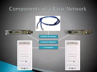
Module 4.0: Network Components • Repeater • Hub • NIC • Bridges • Switches • Routers • VLANs K. Salah
Hardware Components • Repeater • Layer 1 device that provides physical and electrical connections. • It receives signals from one cable segment, regenerates, retimes, and amplifies them, and then transmits these “revitalized” signals to another cable segment. • Transmits in both directions • Joins two segments of cable • No buffering • No logical isolation of segments • Hub • Used to describe a repeater • Can be “repeater hub”, “switching hub”, bridging hub”. • NIC • Network Interface Card • Performs layer-2 functions: framing, error detection, and flow control. • Performs layer-1 functions by converting the bits into electrical signals using appropriate coding scheme. K. Salah
Bridges • Layer 2 devices • Interconnects two or more individual LANs or LAN segments. • Desirable for separating traffic among segments. A segment is part of a LAN in which traffic is common to all nodes, i.e. it is a single continuous conductor, though it may include repeaters. • Can be used to connect different speeds/physical layer types of networks together (10BaseT to 100Base F) • Split the segment with bridges/switches, if link utilization is more than 30%. • Store-and-forward devices. They capture the entire frame before deciding whether to filter or forward it. Frames with bad CRC are not forwarded. • Minimal buffering to meet peak demand K. Salah
Switches • Switches can operate at different layers: layer 2, 3, 4, and 7.. • Basically a switch is hardware based, not software based. • Three types of layer 2 switches: • Store-and-Forward Switch • Similar to store-and-forward bridge. Store entire frame, check for errors, and then switch to the other ports, based on the destination MAC address. • Cut-Through Switch • The transmission of frame begins as soon as it reads the destination MAC address. Two switch fabric/matrix designs: • Crossbar • Backplane with bus speed > aggregate port speeds • Hybrid Switch • Reliability: store-and-forward. Turn ON when errors are high. • Low latency: cut-through. Turn ON when errors are low. K. Salah
Routers vs. Switches • The primary difference is one semantics. Switches historically infer CO links; routers use CL links. Traditionally, routers have performed router table lookups and packet forwarding in software. • Layer-2 Switches start having routing functionality, and Layer-3 routers start having ASIC (Application Specific Integrated Circuit) switching technology for packets. • Layers 2 and 3 are merging and it is becoming difficult to distinguish between switches and routers. • Layer 3 or IP switching: routing IP packets in ASIC, e.g, MPLS. • Layer 4/7 switching is a new and emerging area, called information content switching. • Layer 4: direct all traffic based on TCP destination port. • All traffic with destination TCP port 80, is directed to a switch port where a web cache resides. • Layer 7: direct traffic based on information used in the payload. • Examine URL GET request. If request for image, direct it request to an optimized image server port. K. Salah
VLANs • VLAN is a logical grouping of nodes using Ethernet switches. Nodes don’t need to be connected physically to the same switch. A broadcast frame will be heard by all nodes within VLAN. • Benefits: • Isolates broadcasts • Frees up network from physical locations • Easily shares resources. A server can be part of multiple VLANs. • Performance. Easily can be enhanced by creating new VLANs. • Security. By containing who can listen to broadcast. • VLAN Membership (implicit tagging) • Port-based • MAC-based • Layer 3/IP • Combination of the above K. Salah