Download
1 / 46
460 likes | 1.29k Views
Turbine Fan Trim Balance. . Goals for this Seminar. Each attendee should Understand Basic Vibration Understand the Fundamentals of Fan Trim Balancing Understand Why Balancing is Beneficial. Overview. What is vibration? What are the effects of vibration? How is vibration measured?

E N D
Goals for this Seminar • Each attendee should • Understand Basic Vibration • Understand the Fundamentals of Fan Trim Balancing • Understand Why Balancing is Beneficial
Overview • What is vibration? • What are the effects of vibration? • How is vibration measured? • What are the options in reducing vibration? • How is vibration analyzed when balancing?
What is Vibration? • For the purpose of fan trim balance in a Turbofan Engine, vibration can be described as the unwanted, unproductive, cyclic oscillation of the fan assembly about its rotational axis.
REMEMBER... • All noise and/or vibration is not generated by an imbalance in the fan. • To verify the vibration source, a vibration survey should be conducted and manufacturers’ limitations adhered to.
Examples of Vibration-Related Complaints • Passenger complaints of noise in the cabin • Higher than normal EVM (Engine Vibration Monitoring) system indications • Physical movement of airframe (buzz in the seat, yoke, rudder pedals) • Malfunctioning or failed avionics
What Are the Effects of Vibration? • Vibration excites natural frequencies causing significant vibration at the components. • The expended energy from vibration causes wear of components, reduced performance, passenger discomfort and reduced fuel economy.
How Is Vibration Measured? • Sensor Types • Sensor Engineering Units (EUs) • Characteristics of Different Sensor Types • Sensor Specifications • Sensor Mounting
How Is Vibration Measured? • Sensor Types • Displacement - Measures physical change of position. • Velocity - Measures the rate of change of displacement with time. • Acceleration - Measures the rate of change of velocity with time.
How Is vibration measured? • Engineering Units • Mils (0.001 inches) - displacement • IPS (Inches Per Second) - velocity • gs (equivalent gravities) - acceleration
How Is Vibration Measured? • Modifiers • Peak • Peak to Peak • Average • RMS
How Is vibration measured? • Sensor Characteristics • Displacement Sensor • Measure change in position • Typically reported in mils Peak to Peak • More sensitive to low frequencies • Directly related to movements due to imbalance • Seldom used in balance. (However, displacement units (Mils) are sometimes used)
How Is Vibration Measured? • Sensor Characteristics • Velocimeters/Velometers • Measure velocity • Typically reported in IPS Peak • More sensitive to medium frequencies • Directly related to energy from imbalance • Often used in balance
How Is Vibration Measured? • Sensor Characteristics • Accelerometers • Measure acceleration • Typically reported in g’s • More sensitive to higher frequencies • Directly related to force caused by imbalance • Used in balancing (after conversion to velocity or displacement)
How Is vibration measured? • Sensor Characteristics • Specifications • Sensitivity (millivolts per Engineering Unit) • Temperature range • Physical size • Physical weight • Mounted resonance frequencies • Use manufacturer recommendations for engine
How Is Vibration Measured? • Sensor Characteristics • Sensor Mounting • Use engine manufacturer recommended mount • Mount sensor per manufacturer instructions
Options for Reducing Vibration • Remove and replace the faulty component. • Repair the faulty component. • Use active cancellation systems. • Dynamically balance the fan.
How Is Vibration Analyzed • A vibration sensor measures vibration in a given direction. • The once per revolution tach signal provides a timing reference from which the phase angle is calculated. • The relationship between the two is used to identify the magnitude of the vibration and the phase angle or radial location of the heavy spot on the fan.
How Is Vibration Analyzed • The vibration sensor generates an electrical signal as the heavy spot on the fan passes its location and sends the signal to the analyzer. The analyzer measures its voltage, the time of its occurrence and records these in memory. • The reflective tape triggers a response in the LASETACH® as it passes the optical laser beam. The LASETACH then sends an electrical signal to the analyzer. The time of arrival is recorded in the analyzer’s memory.
How Is Vibration Analyzed • The vibration sensor and reflective tape are installed on the engine. The LASETACH is mounted up to 30 feet in front of the inlet and aimed at the spinner where the tape is to trigger the tach event. The mass (heavy spot on the fan) is located by relative occurrence of the tach event (reflective tape passing in front of laser beam) and mass passage at the radial sensor location. In this slide, the tach event is about to occur and the vibration event is near zero between the positive and negative vibration events.
How Is Vibration Analyzed • As rotation of the fan continues, the mass is now located opposite the vibration sensor. This is the point of the maximum negative going peak in the sine wave. From this point, the mass will move back toward the zero crossing (between negative and positive) then upward toward the sensor. This compresses the piezoelectric element inside which generates the voltage output. That voltage is sent along the connecting cable to the analyzer where it is measured and converted to engineering units (Mils, gs, IPS).
How Is Vibration Analyzed • The mass is about to enter a point in the rotation where the positive upward movement begins in the vibration event. The strength of the electrical signal increases from this point and peaks as the mass reaches the sensor location.
How Is Vibration Analyzed • In this slide the mass, or heavy spot on the fan, is approaching the position of the vibration sensor. Notice that the reflective tape (now at the 3:00 position) has traveled 270 degrees since the tach event. The maximum amplitude of the vibration, as measured by the vibration sensor occurs here.
Fundamentals of Balancing • Overview • What information is required • How the data is collected • How the balance solution is computed • How the balance weight is installed
Fundamentals of Balancing • What information is required? • Engine speed(s) for balancing • The vibration amplitude for each speed • The angular reference (phase) of the vibration for each speed • Influence on the fan of weight addition for each speed
Fundamentals of Balancing • How to select balance speeds. • Use Manufacturers Recommended Speeds • Use Speed of the complaint • Use Vibration Survey to Select Speed(s)
Fundamentals of Balance • What is an Influence? • A ratio of how much weight is required to counter a measured out of balance condition • Typical units are (grams/IPS) with a phase lag • It is used to compute a balance solution • It can be estimated for the first run • It should be refined on subsequent runs from actual vibration measurements
Fundamentals of Balance • How is the required data collected? • Install vibration sensor • Install speed sensor • Run aircraft • Collect average magnitude and phase data for each speed and sensor of interest
Fundamentals of Balance • How is balance solution calculated? • The balancer calculates a solution based on the vibration magnitude and phase data collected for each speed • It presents the solution to the user, such as “Place 2 Grams of weight at 90 degrees” or “Install a -2 weight in hole number 2” • Install/record the weight added and its location • Run the engine again to verify predicted results • Refine solution if necessary
Fundamentals of Balance • How is the solution refined? • Actual vibration changes and weight additions are used to compute a more accurate estimate of the influence at each speed • This recomputed “accurate” influence is used to estimate a new balance weight • Balancer should record actual weights added • Influence should be further refined on each additional run
Fundamentals of Balance • Notes on calculated solutions • All turbine fans are different! • Sophisticated balance equipment adjusts for these differences after the first weight placement • Vibration will not always go down with the first weight placement • If the vibration is not reduced by the second adjustment, check mechanical condition and/or balance process
Fundamentals of Balance • How are the balance weights installed? • On first run, place closest weight in closest hole • On later runs, split weights between holes for more accurate solution • If removing the spinner, index it so it can be reinstalled in the same location and orientation • Beware of different length bolts used in weight placement or spinner attachment • Use the engine manufacturers instructions
Fundamentals of Balance • Where to place the weights • NOTE: If your balancing equipment gives you specific bolt or hole locations and class weight information for addition of trim weights, these steps are not necessary.
Fundamentals of BalanceWhere to place the weights • 1. Index the fan back to the point where the tach event occurs. (0 or 360 degrees) • 2. Rotate the fan assembly, in the direction of rotation, the number of degrees specified in the balance solution. The location for the weight is now adjacent to the vibration sensor.
Fundamentals of Balance • How is weight split between holes? • Compute weights between holes so that the total effective weight is the same as the desired weight • If class weights (a fixed set of available weights are used on the engine), use an optimizing algorithm to select the best weight combination to approximate the desired weight.
Fundamentals of Balance • Summary of Steps: • Install vibration sensor • Install the once per revolution tachometer • Perform a vibration survey and verify balance necessary • Remove any existing trim balance weights • Collect magnitude and phase data for each speed of interest • Compute weight necessary for balance
Fundamentals of Balance • Summary of Steps: (continued) • Convert the solution into a class weight for the required weight and to a bolt or hole number for the angle. • Present the solution to user as “Place -2 weight at hole #3" for instance • Ask user for the actual weights installed • Run the engine again and collect vibration data.
Fundamentals of Balance • Summary of Steps: (continued) • Verify predicted results. • If acceptable, balance job is complete • If not, compute refined estimate of the influence and continue the process at computing weight
Why Is Balancing Beneficial? • Reduces vibration and noise induced stress on crew and passengers. • Airframe, avionics, and engine systems sustain less damage. Useful life is extended. • Operational efficiency is increased because the energy previously used to generate noise and vibration is now used to generate thrust.
ReviewVibration • What is vibration • Examples of vibration and related complaints • Effects of vibration • How vibration is measured • How vibration is analyzed for balancing
ReviewWhy is Balancing Beneficial • Reduces vibration and noise induced stress on crew and passengers. • Airframe, avionics, and engine systems sustain less damage. Useful life is extended. • Operational efficiency is increased because the energy previously used to generate noise and vibration is now used to generate thrust.
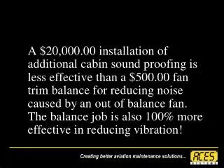
Conclusion • If you’ve already bought additional insulation for your company jet to reduce noise, you didn’t get what you paid for. For much less money and time a Fan Trim Balance is the best choice for a quiet smooth engine.
Contact www.acessystems.com 1-865-671-2003 sales@acessystems.com