Download

1 / 46
570 likes | 895 Views
Class 09 Content Addressable Memories. Cell Design and Peripheral Circuits. Semiconductor Memory Classification. FIFO: First-in-first-out LIFO: Last-in-first-out (stack) CAM: Content addressable memory. Memory Architecture: Decoders. pitch matched. line too long. 2D Memory Architecture.

E N D
Class 09Content Addressable Memories Cell Design and Peripheral Circuits
Semiconductor Memory Classification FIFO: First-in-first-out LIFO: Last-in-first-out (stack) CAM: Content addressable memory
Memory Architecture: Decoders pitch matched line too long
2D Memory Architecture bit line 2k-j word line Aj Aj+1 Row Address storage (RAM) cell Row Decoder Ak-1 m2j Column Address A0 selects appropriate word from memory row A1 Column Decoder Aj-1 Sense Amplifiers amplifies bit line swing Read/Write Circuits Input/Output (m bits)
3D Memory Architecture Row Addr Column Addr Block Addr Input/Output (m bits) Advantages: 1. Shorter word and/or bit lines 2. Block addr activates only 1 block saving power
Hierarchical Memory Architecture Row Address Column Address Block Address Global Data Bus Control Block Selector Global Amplifier/Driver Circuitry I/O • Advantages: • shorter wires within blocks • block address activates only 1 block: power management
Read-Write Memories (RAM) • Static (SRAM) • Data stored as long as supply is applied • Large (6 transistors per cell) • Fast • Differential signal (more reliable) • Dynamic (DRAM) • Periodic refresh required • Small (1-3 transistors per cell) but slower • Single ended (unless using dummy cell to generate differential signals)
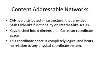
What is CAM? • Content Addressable Memory is a special kind of memory! • Read operation in traditional memory: • Input is address location of the content that we are interested in it. • Output is the content of that address. • In CAM it is the reverse: • Input is associated with something stored in the memory. • Output is location where the associated content is stored.
Type of CAMs • Binary CAM (BCAM) only stores 0s and 1s • Applications: MAC table consultation. Layer 2 security related VPN segregation. • Ternary CAM (TCAM) stores 0s, 1s and don’t cares. • Application: when we need wilds cards such as, layer 3 and 4 classification for QoS and CoS purposes. IP routing (longest prefix matching). • Available sizes: 1Mb, 2Mb, 4.7Mb, 9.4Mb, and 18.8Mb. • CAM entries are structured as multiples of 36 bits rather than 32 bits.
Data In 1 0 1 1 0 0 0 1 0 1 0 1 0 1 0 1 0 1 1 0 1 1 0 0 0 0 2 1 1 0 1 0 0 1 1 0 1 0 1 0 1 0 1 0 4 3 1 0 1 1 1 1 0 1 1 1 0 1 1 0 0 0 0 Address In 1 0 1 1 0 0 0 1 3 4 1 0 1 1 0 0 0 1 2 1 1 0 1 0 0 1 1 Address Out 1 0 1 1 0 0 0 1 5 1 1 1 0 1 1 0 0 3 1 0 1 1 0 0 0 1 4 1 0 1 1 1 0 0 0 5 1 1 1 0 0 0 1 1 1 0 1 1 0 0 0 1 Data Out CAM: Introduction • CAM vs. RAM
Memory Hierarchy The overall goal of using a memory hierarchy is to obtain the highest-possible average access speed while minimizing the total cost of the entire memory system. Microprogramming: refers to the existence of many programs in different parts of main memory at the same time.
Memory Address Map The designer of a computer system must calculate the amount of memory required for the particular application and assign it to either RAM or ROM. The interconnection between memory and processor is then established from knowledge of the size of memory needed and the type of RAM and ROM chips available. The addressing of memory can be established by means of a table that specifies the memory address assigned to each chip. The table, called a memory address map, is a pictorial representation of assigned address space for each chip in the system. Memory Configuration (case study): Required: 512 bytes ROM + 512 bytes RAM Available: 512 byte ROM + 128 bytes RAM
Associative Memory The time required to find an item stored in memory can be reduced considerably if stored data can be identified for access by the content of the data itself rather than by an address. A memory unit access by content is called an associative memory or Content Addressable Memory (CAM). This type of memory is accessed simultaneously and in parallel on the basis of data content rather than specific address or location. When a word is written in an associative memory, no address is given. The memory is capable of finding an empty unused location to store the word. When a word is to be read from an associative memory, the content of the word or part of the word is specified. The associative memory is uniquely suited to do parallel searches by data association. Moreover, searches can be done on an entire word or on a specific field within a word. Associative memories are used in applications where the search time is very critical and must be very short.
Argument register (A) Key register (K) Match register Input Associative memory array and logic M Read m words Write n bits per word Output Hardware Organization
A A A 1 j n K K K 1 j n M C C C Word 1 1 11 1j 1n M C C C Word i i i1 ij in M C C C Word m m m1 mj mn Bit 1 Bit j Bit n Associative memory of an m word, n cells per word
A K i j Input Write R S Match M To F i logic ij Read Output One Cell of Associative Memory
A A A K K K 1 2 n 1 2 n F' F F' F F' F i1 i1 i2 i2 in in M i Match Logic cct.
SL1c SL1 ML N5 N7 BL1_cell BL1c_cell N6 N8 P1 P2 N4 N3 N1 N2 BL1c BL1 WL CAM: Introduction • Binary CAM Cell
Input Keyword Input Keyword 1 0 1 1 0 X X X 1 0 1 1 0 0 0 1 1 1 0 1 0 1 0 X 0 1 0 0 1 0 1 0 1 0 1 0 1 0 1 1 0 1 0 1 1 0 0 0 Match Match 1 1 0 1 1 0 1 0 1 1 1 0 1 1 0 0 0 X 2 1 X 0 1 0 0 1 1 2 1 1 0 1 0 0 X X 4 4 3 1 0 1 1 1 0 0 0 3 1 0 1 1 1 X X X 1 0 1 1 0 1 0 1 1 Match 4 1 0 1 1 0 0 1 0 4 1 0 1 1 X X X X Match 5 1 1 1 0 0 X 0 0 5 1 1 1 X X X X X CAM: Introduction • Ternary CAM (TCAM)
Comparison Logic SL1 SL2 ML BL1c BL2c BL2 BL1 RAM Cell RAM Cell WL CAM: Introduction • TCAM Cell • Global Masking SLs • Local Masking BLs
SL2 SL1 ML N5 N7 BL1_cell BL2_cell N6 N8 N3 N4 BL2 BL1 WL CAM: Introduction • DRAM based TCAM Cell • Higher bit density • Slower table update • Expensive process • Refreshing circuitry • Scaling issues (Leakage)
SL1 SL2 ML BL1c_cell BL2c_cell BL1 BL1c BL2c BL2 WL CAM: Introduction • SRAM based TCAM Cell • Standard CMOS process • Fast table update • Large area (16T)
Search Lines (SLs) SL Drivers ML Sense Amplifiers SL1(0) SL2(0) SL1(143) SL2(143) MLSO(0) ML0 MLSA Match Lines (MLs) BL2c(N) BL1c(N) BL1c(0) BL2c(0) CAM Cell (143) CAM Cell (0) MLSO(255) ML255 MLSA BL1c(N) BL1c(0) BL2c(0) BL2c(N) CAM Cell (143) CAM Cell (0) CAM: Introduction • Block diagram of a 256 x 144 TCAM
CAM: Introduction • Why low-power TCAMs? • Parallel search Very high power • Larger word size, larger no. of entries High power • Embedded applications (SoC)
CAM: Design Techniques • Cell Design: 12T Static TCAM cell* • ‘0’ is retained by Leakage (VWL ~ 200 mV) • High density • Leakage (3 orders) • Noise margin • Soft-errors (node S) • Unsuitable for READ
ML_NOR MM CAM Cell (N) CAM Cell (1) CAM Cell (0) CAM Cell (N) CAM Cell (1) CAM Cell (0) ML_NAND M SA SA NAND-type CAM NOR-type CAM SL1c SL1 SL1 SL1c BL1 VDD BL1c BL1 VDD BL1c WL WL CAM: Design Techniques • Cell Design: NAND vs. NOR Type CAM • Low Power • Charge-sharing • Slow
VDD MLSO VDD PRE ML MM MM CAM: Design Techniques • MLSA Design: Conventional • Pre-charge ML to VDD • Match VML = VDD • Mismatch VML = 0
CAM: Design Techniques • Low Power: Dual-ML TCAM • Same speed, 50% less energy (Ideally!) • Parasitic interconnects degrade both speed and energy • Additional ML increases coupling capacitance
SL1 SL2 ML N9 N11 BL1c_cell BL2c_cell N10 N12 P1 P2 P3 P4 BL2c BL1 BL1c BL2 ‘1’ ‘0’ N3 ‘0’ N4 N7 N8 ‘0’ ‘1’ ‘0’ ‘1’ ‘1’ N1 N2 N5 N6 WL CAM: Design Techniques • Static Power Reduction • 16T TCAM: Leakage Paths* * N. Mohan, M. Sachdev, Proc. IEEE CCECE, pp. 711-714, May 2-5, 2004
MLSO [0] ML [0] Voltage Margin ML [1] CAM: Design Techniques • Static Power Reduction • Side Effects of VDD Reduction in TCAM Cells • Speed: No change • Dynamic power: No change • Robustness • VDD Volt. Margin (Current-race sensing)
CAM for Routing Table Implementation • CAM can be used as a search engine. • We want to find matching contents in a database or Table. • Example Routing Table Source: http://pagiamtzis.com/cam/camintro.html
Simplified CAM Block Diagram • The input to the system is the search word. • The search word is broadcast on the search lines. • Match line indicates if there were a match btw. the search and stored word. • Encoder specifies the match location. • If multiple matches, a priority encoder selects the first match. • Hit signal specifies if there is no match. • The length of the search word is long ranging from 36 to 144 bits. • Table size ranges: a few hundred to 32K. • Address space : 7 to 15 bits. Source: K. Pagiamtzis, A. Sheikholeslami, “Content-Addressable Memory (CAM) Circuits and Architectures: A Tutorial and Survey,” IEEE J. of Solid-state circuits. March 2006
CAM Memory Size • Largest available around 18 Mbit (single chip). • Rule of thumb: Largest CAM chip is about half the largest available SRAM chip. • A typical CAM cell consists of two SRAM cells. • Exponential growth rate on the size Source: K. Pagiamtzis, A. Sheikholeslami, “Content-Addressable Memory (CAM) Circuits and Architectures: A Tutorial and Survey,” IEEE J. of Solid-state circuits. March 2006
CAM Basics • The search-data word is loaded into the search-data register. • All match-lines are pre-charged to high (temporary match state). • Search line drivers broadcast the search word onto the differential search lines. • Each CAM core compares its stored bit against the bit on the corresponding search-lines. • Match words that have at least one missing bit, discharge to ground. Source: K. Pagiamtzis, A. Sheikholeslami, “Content-Addressable Memory (CAM) Circuits and Architectures: A Tutorial and Survey,” IEEE J. of Solid-state circuits. March 2006
CAM Advantages • They associate the input (comparand) with their memory contents in one clock cycle. • They are configurable in multiple formats of width and depth of search data that allows searches to be conducted in parallel. • CAM can be cascaded to increase the size of lookup tables that they can store. • We can add new entries into their table to learn what they don’t know before. • They are one of the appropriate solutions for higher speeds.
CAM Disadvantages • They cost several hundred of dollars per CAM even in large quantities. • They occupy a relatively large footprint on a card. • They consume excessive power. • Generic system engineering problems: • Interface with network processor. • Simultaneous table update and looking up requests.
CAM structure • The comparand bus is 72 bytes wide bidirectional. • The result bus is output. • Command bus enables instructions to be loaded to the CAM. • It has 8 configurable banks of memory. • The NPU issues a command to the CAM. • CAM then performs exact match or uses wildcard characters to extract relevant information. • There are two sets of mask registers inside the CAM.
CAM structure • There is global mask registers which can remove specific bits and a mask register that is present in each location of memory. • The search result can be • one output (highest priority) • Burst of successive results. • The output port is 24 bytes wide. • Flag and control signals specify status of the banks of the memory. • They also enable us to cascade multiple chips.
CAM Features • CAM Cascading: • We can cascade up to 8 pieces without incurring performance penalty in search time (72 bits x 512K). • We can cascade up to 32 pieces with performance degradation (72 bits x 2M). • Terminology: • Initializing the CAM: writing the table into the memory. • Learning: updating specific table entries. • Writing search key to the CAM: search operation • Handling wider keys: • Most CAM support 72 bit keys. • They can support wider keys in native hardware. • Shorter keys: can be handled at the system level more efficiently.
CAM Latency • Clock rate is between 66 to 133 MHz. • The clock speed determines maximum search capacity. • Factors affecting the search performance: • Key size • Table size • For the system designer the total latency to retrieve data from the SRAM connected to the CAM is important. • By using pipeline and multi-thread techniques for resource allocation we can ease the CAM speed requirements. Source: IDT
Management of Tables Inside a CAM • It is important to squeeze as much information as we can in a CAM. • Example from Netlogic application notes: • We want to store 4 tables of 32 bit wide IP destination addresses. • The CAM is 128 bits wide. • If we store directly in every slot 96 bits are wasted. • We can arrange the 32 bit wide tables next to each other. • Every 128 bit slot is partitioned into four 32 bit slots. • These are 3rd, 2nd, 1st, and 0th tables going from left to right. • We use the global mask register to access only one of the tables.
Example Continued • We can still use the mask register (not global mask register) to do maximum prefix length match.