Download

1 / 34
350 likes | 540 Views
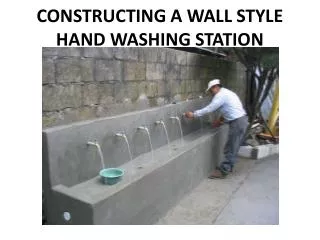
CONSTRUCTING A WALL STYLE HAND WASHING STATION. Disclaimer.

E N D
Disclaimer The following power point presentation assumes the user is familiar with plumbing, concrete construction techniques and has a basic knowledge of geometry so as to select the proper dimensions of the hand wash station. Further, the exact dimensions will depend on the design criteria, but at a minimum, a hand wash station should have a clean out and shut off valves; entry of water from the water source; and sufficient faucets to serve the distribution system.
Site Plan Hand wash station floor 10 cm depth 1.5m Buried concrete box with top of lid at grade for shutoff valve 3.3m 2” PVC drain line buried 50 cm below grade 1/2” galvanized feed line 1.5m dia hole from grade to 0.5m depth This area to be filled with large stone and concrete 1.0m dia hole from 0.5m below grade to 3.5m to 5m below grade Drainage pit NOTE: A CIRCULAR AREA, 2m IN DIAMETER SHOULD BE KEPT CLEAR FOR MIXING OF CONCRETE
Materials Galvanized Pipe Four (4) ½” 90° Elbows Nine (9) ½” couples Eight (8) ½” water tap valves One (1) ½” gate valve (shutoff) Nine (9) ½” X 10cm Nipples Seven (7) ½” x 35cm Nipples One (1) Length (6m) ½” Tube Eight (8) ½” Tees PVC Pipe Two (2) ½” Male PVC to Galv Adaptor One (1) Length (6m) ½” Pipe Two (2) Lengths (12m) 2” Drain Pipe Six (6) 2” Drainage Tees 1/8 Gallon PVC glue Two (2) 2” Female Threaded Adaptors Two (2) 2” Male Threaded Plugs Two (2) rolls Teflon tape Drain covers (see slide #24, “Drain Layout”) Two (2) lbs 2-1/2” Nails Two (2) lbs 4” Nails Wood for formwork Two (2) lengths 12´X2”X4” Two (2) cubic meters Large stone (6 to 12 in dia.) Thirteen (13) 3/8”x 6m reinforcing steel bars Five (5) lbs Tie Wire Ten (10) 45kg bags of cement 1.5 Cubic meters Sand 1.5 cubic meters Gravel Water
Site Preparation Cut enough room for the entire handwash station to sit on solid, flat ground. A flat area to will also be needed to mix concrete. Concrete mixed here Construct a wooden mould for the base of the hand wash station Smooth and compact floor area
Drainage Pit • Dig hole with 1.5 m inside diameter to 0.5m depth • CAUTION: DO NOT DIG DRAINAGE PIT IN FILL SOIL. WHEN IN DOUBT USE SHORING
Cover sides with stone • Be sure to maintain at least 1.0m inside diameter • Add concrete to outside of stone to set in place • Leave opening for drainage pipe
Drainage Pit Dig 1m inside diameter hole to additional 3m to 5m depth Depth is a function of the absorption of the soil. In clay soils, a 5.5m total depth will be needed. Hole will extend to 3.5m to 5.5 below grade.
Hand Wash Station Floor Use a level to ensure that the form is level, so once the cement is poured, the base is level Ensure forms are held firmly in place Concrete will not be poured in this area. Rebar for hand wash station will fit inside this area. 4 to 6 inch diameter stone is placed to cover the ground Galvanized water line in place Leave a minimum gap of 5 cm between rebar and form to allow concrete to fill this area. Do not place stone between rebar and form. Drain pipe in place
Wood Form 5 cm Concrete 5 cm Rebar 10 cm Rocks Hand Wash Station FloorSection View
Hand Wash Station FloorRebar Layout 3.1 m Two (2) Equal spaces at 70 cm 1.4 m Seven (7) Equal spaces at 45 cm
Attach the rods using small pieces of metal wire, ensuring that once tied, there are no sharp tails left. For rods that are parallel to each other, a simple wrap round and twist with a pair of pliers, will be sufficient. Allow at least 10 cm overlap of bars
For rods that are perpendicular to each other use an “iron workers knot “ illustrated in the pictures opposite.
For the base, use a sand, gravel to cement ratio by volume of 3 parts gravel 1.5 parts sand 1 part cement • It is not necessary to smooth the tank floor to perfection. A finishing layer will be added as a last step.
Galvanized Piping Layout • NOTE: DO NOT ACCEPT A SUBSTITUE FOR GALVANIZED PIPE
Piping Layout (Plan) To shutoff valve ½” X 35cm Nipple Seven (7) Equal spaces at 40 cm ½” Galvanized Tee ½” Galvanized Elbow ½” X 10cm Galvanized Nipple ½” Galvanized Pipe or Nippe (Length Varies) ½” Galvanized Couple • NOTE: All connections should be made using Teflon (tape or paste) to prevent water leakage
Piping Layout (Elevation) ½” Galvanized Elbow ½” Galvanized Pipe or Nipple (Length Varies) 85 cm 130 cm Top of hand wash station floor This section of pipe should be buried
Measurements for an 8 tap hand wash station 45 cm 10 cm 320 cm 60 cm 10 cm 25 cm 10 cm 55 cm
Hand Wash StationRebar Layout (Plan) 12 vertical bars, 100 cm tall, at 25 cm spacing 5 cm 300 cm 5 cm 2 vertical bars, 55 cm tall 70 cm 5 cm 30 cm 30 cm 5 cm 70 cm 12 vertical bars, 55 cm tall, at 25 cm spacing (Horizontal rebar not shown)
Hand Wash StationRebar Layout (Section) 27.5cm 27.5cm 10cm THREE (3) HORIZONTAL BARS, ALL AROUND
Drain Covers • A 2” PVC cap can be used for a drain cover by simply drilling 3/8” holes
Drain Layout (Plan) Five (5) Equal spaces at 64 cm 2” Drainage Tee 2” Female Adaptor To drainage pit (buried 50cm below grade) 2” Threaded Plug 2” Drainage Pipe (length varies) • NOTE: All connections should be made using Teflon (tape or paste) to prevent water leakage
Drain Layout (Elevation) 10 cm 35 cm Top of hand wash station floor This section of pipe should be buried 50cm below grade and feed into the drainage pit • Cleanout: 2” Threaded plug screwed into 2” Female Adaptor (See Next Slide) • A drain cover should be attached to the end of the 10cm section of pipe. This cover will sit at the base of the sink.
Cleanout • Cleanout Plug or Tapon de Limpieza in Spanish • Threaded plug should be removable from exterior or hand wash station • One cleanout is placed on either end of the main drain pipe (see slide #24 “Drain Layout”) Cleanout in Place (stuffed with paper during concrete pour)
Formwork placed • 5 cm clear spacing should be maintained between rebar and formwork • The area in the center of the rebar will be filled with large stone, then concrete. • Place drainline before adding concrete
Pouring Concrete • Concrete is mixed to obtain a homogeneous mixture • Water is added until the desired consistency is obtained • Concrete is then poured into the form
Shutoff Valve Box • Rebar placement shown below 6 bars at 10 cm spacing LID: TOP VIEW 6 bars at 10 cm spacing 4 bars at 16.67cm spacing BOX: R SIDE VIEW • A piece of rebar should be bent as seen above to serve as a handle for the lid • A thickness of 10 cm should be maintained on box walls, floor, and lid • The box has 4 walls without top or bottom • For shutoff valve box location see slide #4 “Site Plan.” Choose location per site conditions. 3 bars at 25cm spacing BOX: L SIDE VIEW 3 bars at 25cm spacing
Finishing Touches • A final layer of cement plaster is added to give the station a smooth finish • Mix concrete for finishing layer with 2 parts sand to 1 part cement • Concrete on the sink should be sloped towards the drain lines
Ready to Use! Add step for little ones