Download
1 / 28
290 likes | 633 Views
The Proposed Materials Test Station at LANSCE Eric Pitcher Los Alamos National Laboratory Presented at the Workshop on High-Power Targetry for Future Accelerators Brookhaven National Laboratory September 8, 2003.

E N D
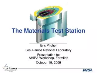
The Proposed Materials Test Stationat LANSCE Eric Pitcher Los Alamos National Laboratory Presented at the Workshop on High-Power Targetry for Future AcceleratorsBrookhaven National Laboratory September 8, 2003
The Advanced Fuel Cycle Initiative and GEN IV programs require a fast neutron spectrum facility for fuels and materials testing • Advanced fuel concepts (e.g., nitride, metallic dispersion, fertile-free) are proposed for closing the nuclear fuel cycle, as well as for some GEN IV reactors • Nearly all nuclear waste transmuter concepts, and most GEN IV reactor concepts, operate with a fast neutron spectrum • Fuel cladding must be tested in prototypic radiation environments with appropriate coolants (e.g., Pb-Bi)
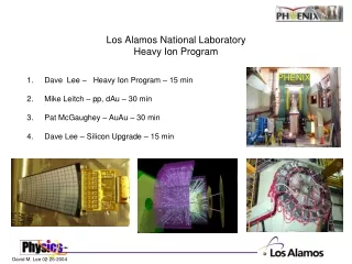
There is a clear need for a U.S. fast spectrum irradiation facility • With the termination of the FFTF, there is no longer a domestic fast neutron spectrum irradiation facility • There are a limited number of viable facilities abroad: • PHENIX (France) • JOYO (Japan) • BOR-60 (Russia) • Irradiation campaigns abroad are time-consuming and expensive • Irradiation of eight 11-cm-high fuel pins in PHENIX by AFCI will take four years from initial discussions with CEA to the start of irradiation, with a cost for irradiation services of $5M
LANSCE is a cost-effective and logical choice for locating a fast-spectrum irradiation facility • A new fast reactor would cost at least $800M • LANSCE proton beam power is 800 kW (1 mA at 800 MeV)
Materials Test Station (MTS)Functions and Requirements • Intense fast neutron flux (up to 1015 n.cm–2.s–1) over a 1-liter volume with minimal proton flux contamination • High burnup of fuel specimens (~6%/year) • High damage rate of materials specimens (~7 dpa/year) • Radiation damage environment similar to that encountered in a fast reactor • He/dpa ratio near 0.5 appm/dpa • High proton flux for spallation source materials testing • Separate cooling loops for test specimens • Capability of testing to failure • Negligible reactivity from fuel specimens (deeply subcritical)
The Materials Test Station will be located in an existing experimental area
Experimental Area A in 1971 proton beam path
The A-1 target, shown here during construction in 1973, is the proposed location for the MTS
The MTS 13-foot-diameter vacuum vessel would fit within the existing shielding
The MTS includes a neutron source, irradiation positions, shielding, and vacuum vessel Removable Shielding Vacuum Vessel Target Assembly Existing Shielding Existing Base Plate on top of Concrete Slab Reflector and Shielding Beam Line
The target and irradiation zones will sit on a stalk that is inserted into the vacuum vessel from above
A conceptual design of a flowing Pb-Bi target has been developed
A phased approach in spallation targets is proposed for achieving ever-greater neutron fluxes • Heavy-water cooled clad tungsten target • Extensive development within the Accelerator Production of Tritium program gives high confidence that this target will work reliably • Flowing Pb-Bi target • Moderate risk whose design will draw from lessons learned in the MEGAPIE project • Heavy-watered cooled uranium target • Testing of uranium alloys under proton irradiation is required to validate target lifetimes
proton beamfootprint on target The U-shaped target canister provides excellent target window cooling direction ofcoolant flow
W or Utargetmaterial The U-shaped target canister provides excellent target window cooling proton beamfootprint on target direction ofcoolant flow
MTS takes advantage of the pulsed nature of the LANSCE beam to illuminate two spots on target • Beam frequency is 120 Hz, pulse duration is 1 ms
MTS takes advantage of the pulsed nature of the LANSCE beam to illuminate two spots on target • Beam frequency is 120 Hz, pulse duration is 1 ms • During a single 1-ms pulse, the beam is directed onto one spot on the target
MTS takes advantage of the pulsed nature of the LANSCE beam to illuminate two spots on target • Beam frequency is 120 Hz, pulse duration is 1 ms • During a single 1-ms pulse, the beam is directed onto one spot on the target • During the 8 ms the beam is off between pulses, a dipole magnet directs the beam to the alternate position on the target
MTS takes advantage of the pulsed nature of the LANSCE beam to illuminate two spots on target • Beam frequency is 120 Hz, pulse duration is 1 ms • During a single 1-ms pulse, the beam is directed onto one spot on the target • During the 8 ms the beam is off between pulses, a dipole magnet directs the beam to the alternate position on the target • The next 1-ms pulse hits the other target position
MTS takes advantage of the pulsed nature of the LANSCE beam to illuminate two spots on target • Beam frequency is 120 Hz, pulse duration is 1 ms • During a single 1-ms pulse, the beam is directed onto one spot on the target • During the 8 ms the beam is off between pulses, a dipole magnet directs the beam to the alternate position on the target • The next 1-ms pulse hits the other target position • The beam is rastered vertically at a high frequency (~1 kHz)
Spatial distribution of the proton flux for an LBE-cooled U-10Mo target p.cm–2.s–1.mA–1
Spatial distribution of the neutron flux for anLBE-cooled U-10Mo target n.cm–2.s–1.mA–1
Spatial distribution of the power density for anLBE-cooled U-10Mo target W.cm–3
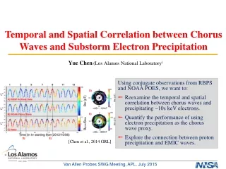
The flux spectrum the MTS with a D2O-cooled U target compares favorably with the FFTF Flux Mean Energy (n.cm–2.s–1) (MeV) . FFTF 1.00×10¹⁵ 0.51 . Upstream MTS 0.35×10¹⁵ 1.7 . Downstream MTS 0.85×10¹⁵ 3.8 .
The MTS can be completed in 3 years at a cost of $20M MTS Schedule and CostFY04 FY05 FY06 FY07 FY08 Installation/Commission Operation/Testing Costs (Operating Funds) $5M $8M $7M $3M $3M
MTS Status • Pre-conceptual design completed in FY02. No work performed in FY03. • Safety authorization plan completed. • MTS is within the existing Environmental Impact Statement. • Total installation cost estimated at $20M, and can be completed in 3 years. • Project will replace an experimental station that is no longer used. It will be installed with operating funds because we are replacing a test station within an existing experimental area. • Seeking authorization from DOE-NE to start work in FY04.
Summary • We need a domestic fast neutron source for materials and fuels irradiations. The alternative is expensive irradiations abroad. • The MTS meets this need at a reasonable cost.