Download
1 / 20
210 likes | 325 Views
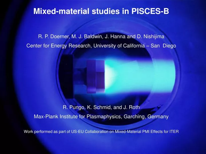
Mixed-material studies in PISCES-B R. P. Doerner, M. J. Baldwin, J. Hanna and D. Nishijima Center for Energy Research, University of California – San Diego R. Pungo, K. Schmid, and J. Roth Max-Plank Institute for Plasmaphysics, Garching, Germany

E N D
Mixed-material studies in PISCES-B R. P. Doerner, M. J. Baldwin, J. Hanna and D. Nishijima Center for Energy Research, University of California – San Diego R. Pungo, K. Schmid, and J. Roth Max-Plank Institute for Plasmaphysics, Garching, Germany Work performed as part of US-EU Collaboration on Mixed-Material PMI Effects for ITER
Outline • Introduction • Technical results • Temporal behavior of chemical erosion suppression • Response of Be/C to thermal transients • Be/W formation conditions • Summary of possible mixed-material implications for ITER
PISCES-B has been modified to allow exposure of samples to Be seeded plasma P-B experiments simulate Be erosion from ITER wall, subsequent sol transport and interaction with W baffles or C dump plates, as well as investigation of codeposited materials using witness plates
A small beryllium impurity concentration in the plasma drastically suppresses carbon erosion -50 V bias, 200ºC, Te = 8 eV, ne = 3 e 12 cm-3 Chemical erosion Physical sputtering
Erosion suppression exhibits a temporal evolution (tBe/C) • Understanding the temporal behavior is critical to determining the fundamental mechanisms responsible for erosion mitigation • PMI modeling codes should be able to reproduce temporal behavior to provide confidence
XPS data shows Be2C formation in resultant mixed-material surface XPS analysis of Be on C sample surface [M. Baldwin et al., in press JNM] • Virtually all C remaining at the surface is bound as carbide (t > tBe/C) • Presence of carbide inhibits chemical erosion of C • Carbide layer reduces sputtering yield of bound Be • Subsequently deposited Be can be more easily eroded • Codeposits are primarily Be once carbide layer forms
If Be acts like B doping, then each Be atom should inhibit two C atoms from chemically eroding • Chemical erosion model [Schenk et al. JNM 220-222(1995)767] predicts boron reduces sp2 component in favor of sp3 hybridization. In other words, each B atoms inhibits a C=C bond, thereby affecting 2 C atoms • In-situ Be seeding data shows similar behavior of chemical erosion mitigation, i.e. each Be surface atom is consistent with inhibiting 2 C atoms from chemically eroding
In-situ Be doping of graphite exhibits similar behavior to boron doping of graphite Temp (K) • Dopant increases retention • Dopant shifts hydrogenic release to lower temperature Time (sec) Solid line Be seeding Dashed line no Be seeding From A. Schenk JNM 220-222(1995)767 (B doping).
Increased retention due to dopant becomes less significant during higher temperature exposures • Solid symbols indicate mixed Be/C surfaces formed during plasma exposure, open symbols are from clean substrate data • Mixed Be/C layers retain more deuterium than either Be samples or carbon samples exposed to similar plasma • Difference in retention becomes less pronounced during higher temperature exposure • Plasma contacting surfaces are not ITER’s main tritium inventory concern
Be first shuts down C chemical erosion, then subsequent Be re-erodes from surface • Evolution of a mixed Be/C surface • Be oven opens at t = 0 sec. • Be ions arriving at t < 50s shut down chemical erosion by forming Be2C surface layer [Baldwin JNM 2006 available on-line] • Once Be2C is formed, subsequent Be arriving (T > 50 s) is more easily eroded and begins coating windows • Be2C surface thickness saturates after carbide forms 50s in this exposure [Baldwin JNM 2006] • Resultant codeposited material is primarily Be [Baldwin JNM 337-339(2005)590]
Be2C layer thickness saturates RBS spectra of P-B samples exposed to unseeded and Be-seeded plasma • Be layer observed after ~3E22 Be+/m2 (i.e 1600 s) accounts for virtually all incident Be • Be layer after 1E23 Be+/m2 (i.e 4800 s) accounts for only ~30% of incident Be • tBe/Cunder these plasma exposure conditions would be ~ 2000 sec From M. Baldwin et al., in press JNM
WPM samples show collection of beryllium-rich codeposits during Be seeding runs Carbon target : 700ºC target exposure Carbon target : 300ºC target exposure More C is detected in codeposits during lower C target temperature exposure (possibly due to a combination of lower chemical erosion yield and/or quicker beryllium carbide layer formation)
Chemical erosion suppression time (tBe/C) depends on several variables that can be varied almost independently Be concentration in plasma Incident ion energy Surface temperature of target From D. Nishijima et al., PSI17.
PISCES chemical erosion mitigation time scaling predicts suppression between ELMs in ITER tBe/Cscale [s] = 1.0x10⁻⁷cBe-1.9±0.1Ei0.9±0.3Gi-0.6±0.3 exp((4.8±0.5)x103/Ts) From D. Nishijima et al., PSI17. • Surface temperature effects reaction rate • Be plasma concentration effects arrival rate at surface • Ion energy effects erosion rate • Ion flux impacts through redeposition • Type of graphite does not seem to play a significant role (ATJ vs. CFC) • Scaling law using these variables has been developed to allow extrapolation to ITER conditions (tBe/CITER~ 6 msec) [cBe = 0.05, Ei = 20 eV, Ts = 1200 K and Gi = 1023 m-2s-1] x X =CFC
Thermal transient experiments: Motivation for positive pulse biasing • PISCES has shown that Be plasma impurities suppress carbon target erosion at temperatures up to 1000°C • ITER will experience large temperature excursions (up to 3800°C) at the carbon dump plates during periodic ELMs • Will the thin, surface Be, Be/C layers survive such dramatic temperature excursions? • How will Be-W react during temperature excursions? • It is possible to simulate the large temperature excursions associated with ITER ELMs in PISCES-B using positive sample biasing during plasma discharges.
Large power loads can be drawn to P-B sample during positive biasing • During 1.5 MW/m2 power pulse graphite surface temperature rises to ~2000°C (by pyrometers) • Bulk graphite temperature rise at back of sample ~20°C during 0.1 s. pulse (thermocouple) • Surface temperature rise is limited by power supplies (IPP has supplied a new power supply as part of US-EU collaboration)
Transient surface heating promotes Be2C formation leading to shorter mitigation times • Pulsing surface temperature to the 1200°C range results in faster chemical erosion suppression • Be2C disassociates at ~2200°C at 1 atm • Beryllium boiling point = 2471°C at 1 atm • D retention during transient surface heating also increases by ~50% both with and without Be plasma seeding Surface temperature during heat pulse ~ 1200°C [from R. Pungo et al., PSI17]
Tungsten beryllide (BexW) formation may plague hot W plasma facing components • Be2W and Be12W appear preferred (Be22W not seen) • Beryllides only form in high temperature W surfaces (> 600°C) • Be diffusion rate into W becomes significant above ~800°C • At high temperature, Be availability (high vapor pressure of Be) on the surface can limit growth rate Measurements from SNLL
Plasma conditions will play a dominant role in determining the impact of beryllides fBe Gplasma(1–Rf) = YD-BeGplasma(1–Rd) + fBeYBe-BeGplasma(1–Rd) +Gevap(1–Re) + Dbulk • At high surface temperature, Be sublimation may prevent significant beryllide formation • Sputtering at higher incident ion energies also tends to prevent significant beryllide formation • Higher incident plasma flux tends to push energy, and temperature, necessary to avoid beryllides to larger values Be covered W surface Uncoated W surface M. J. Baldwin et al., PSI17
How might mixed materials impact ITER? • Due to elevated temperature of C dump plates, carbides will likely form and limit C erosion • If a full C divertor were employed, carbide formation on regions of the baffles, where the temperature is lower, would take longer, resulting in more C erosion and thereby more hard-to-remove tritium • Be deposition on W baffles will likely not result in significant beryllide formation (TW ~ 400°C) • If a full W divertor were used, beryllide formation near the strike points would be a concern (perhaps an issue for the JET ITER-like wall experiments) • Beryllide formation in ITER only appears to be a concern on the W cassette liner ‘louvers’ (that are designed to be hot surfaces)