Download
1 / 110
1.1k likes | 1.27k Views
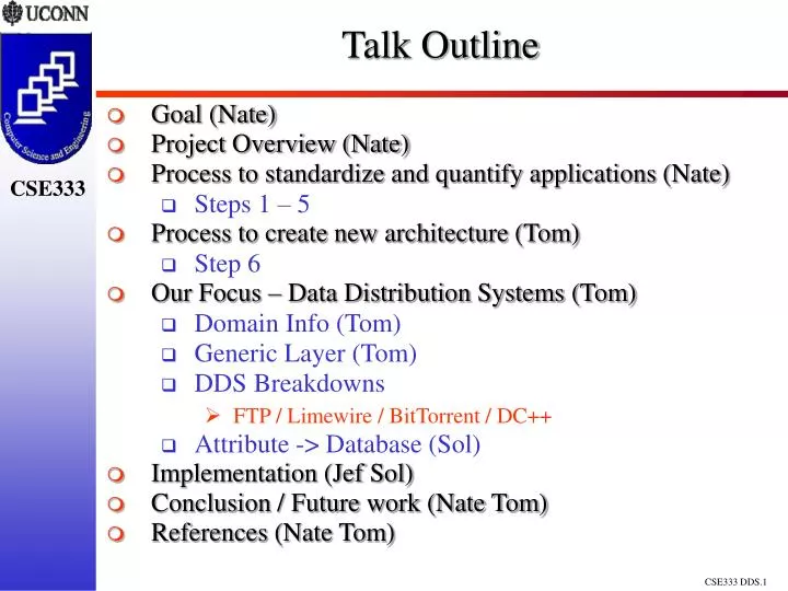
Talk Outline. Goal (Nate) Project Overview (Nate) Process to standardize and quantify applications (Nate) Steps 1 – 5 Process to create new architecture (Tom) Step 6 Our Focus – Data Distribution Systems (Tom) Domain Info (Tom) Generic Layer (Tom) DDS Breakdowns

E N D
Talk Outline • Goal (Nate) • Project Overview (Nate) • Process to standardize and quantify applications (Nate) • Steps 1 – 5 • Process to create new architecture (Tom) • Step 6 • Our Focus – Data Distribution Systems (Tom) • Domain Info (Tom) • Generic Layer (Tom) • DDS Breakdowns • FTP / Limewire / BitTorrent / DC++ • Attribute -> Database (Sol) • Implementation (Jef Sol) • Conclusion / Future work (Nate Tom) • References (Nate Tom)
A System for Creating Specialized DDS Architectures Research and Work By: Tom Puzak Nathan Viniconis Solomon Berhe Jeffrey Peck Project web site: http://www.revrick.net/CSE333/ProjectTimeline.htm
A System for Creating Specialized DDS Architectures - Outline • Goal • Responsibilities • Project Overview • Phase 1: Break down existing applications within the domain. • Steps 1 – 5 • Phase 2: Process to create new architecture • Step 6 • Our Focus – Data Distribution Systems • Domain Info • Generic Layer • DDS Breakdowns • FTP / Limewire / BitTorrent / DC++ • Attribute -> Database • Implementation • Conclusion / Future work • References
Goal • Outline a process of generating an architecture of an application derived from a breakdown of similar applications. Show it can work. • Create a generic procedure that can be extended to a variety of domains within Software Engineering. • Test our procedure with an implementation focusing on the DDS domain.
A System for Creating Specialized DDS Architectures - Outline • Goal • Responsibilities • Project Overview • Phase 1: Break down existing applications within the domain. • Steps 1 – 5 • Phase 2: Process to create new architecture • Step 6 • Our Focus – Data Distribution Systems • Domain Info • Generic Layer • DDS Breakdowns • FTP / Limewire / BitTorrent / DC++ • Attribute -> Database • Implementation • Conclusion / Future work • References
Responsibilities • Universal – Procedures to… • strip applications down to their generic models. • analyze and extend the generic models to a particular application. • tag and store the attributes in an organized way • create a new application using a sum of parts method • Nate – • Webpage Maintenance • http://www.revrick.net/CSE333/ProjectTimeline.htm • BitTorrent Analysis • Tom – • FTP Analysis • Solomon – • Limewire Analysis • Implementation • http://www.berhe.info/cse333/index.php • Jeff – • DC++ Analysis
A System for Creating Specialized DDS Architectures - Outline • Goal • Responsibilities • Project Overview • Phase 1: Break down existing applications within the domain. • Steps 1 – 5 • Phase 2: Process to create new architecture • Step 6 • Our Focus – Data Distribution Systems • Domain Info • Generic Layer • DDS Breakdowns • FTP / LimeWire / BitTorrent / DC++ • Attribute -> Database • Implementation • Conclusion / Future work • References
Project Overview • Goal: Outline a process of generating an architecture of an application derived from a breakdown of similar applications. • Significant Changes • Created generic abstraction from our DDS focus. • Generic Outline • Phase 1 : Break down existing applications within the domain. • Phase 2: Creation of a new architecture. • Extending to the DDS domain • Implementation • http://www.berhe.info/cse333/index.php • Conclusion / Future work
Project Overview-Phase 1 Knowledge Database Application Domain Analysis, Tagging, and Organizing Initial Application Subset x% Generic Models Minimal Subset Standardized Components
Project Overview - Phase 2 Generated Architecture Users Completed Architecture Main Components Knowledge Database Attribute Sets
A System for Creating Specialized DDS Architectures - Outline • Goal • Responsibilities • Project Overview • Phase 1: Break down existing applications within the domain. • Steps 1 – 5 • Phase 2: Process to create new architecture • Step 6 • Our Focus – Data Distribution Systems • Domain Info • Generic Layer • DDS Breakdowns • FTP / Limewire / BitTorrent / DC++ • Attribute -> Database • Implementation • Conclusion / Future work • References
Phase 1 : Overview • Phase 1: Break down existing applications within the domain. • Find suitable subset of the domain • Define the domain using Generic Models (GM) • Break down each application and: • Find shared major components • Create conceptual structural diagrams • Create unified view • Create generic layer • Organize and tag the added functionality • Store the result in a Knowledge Database • Allow additional applications to be added to the Knowledge Database. • Extensions: Behavioral models, GM maintenance.
Phase 1: Finding a suitable subset • Choose applications within the domain that: • Maximize percentage of functionality coverage • Choose applications with • Best: Open source • Worse: Proprietary software but heavily researched • Worst: Small, proprietary, non-analyzed • The end result can only be created from the subset of applications chosen… • so choose wisely! • Create UML 2.0 Class and Use Case diagrams for each application.
Phase 1: Define the domain using Generic Models • Step 1: Find shared major components • Step 2: Break the components into disjoint entities Comp1 Comp2 App1 AppN1 Comp3 … CompN2
Phase 1: Define the domain using Generic Models • Step 3: Create unified view of each component • Combine UML Class Diagrams together into a superset. • Merge classes that overlap between 2+ apps • Create relationships between apps • Step 4: Identify or ‘abstracting out’ generic classes • Identifying generic classes • A class exists that is exactly the same in every app • ‘Abstracting out’ generic classes • Classes exist that contain similar functionality in every application • Create a new class that all applications can inherit
Phase 1: Organize and tag the added functionality • Each application inherits from the GM Class Diagrams. • The Generic Classes are tailored to a more specific instance when inherited from. • Defining the Attributes. • Augmenting it to store additional information • Addition of methods to increase scope of functionality • Store the Attributes in a database. Application Class Generic Class
Phase 1: Extensions • Other aspects can be modeled into a generic layer. • Behavioral Models • Storyboard / Activity / Work-Flow • Security Models • Reuse Models • Multi-layered inheritance tagging • Augment attributes with extracted code segments 2 1
A System for Creating Specialized DDS Architectures - Outline • Goal • Responsibilities • Project Overview • Phase 1: Break down existing applications within the domain. • Steps 1 – 5 • Phase 2: Process to create new architecture • Step 6 • Our Focus – Data Distribution Systems • Domain Info • Generic Layer • DDS Breakdowns • FTP / Limewire / BitTorrent / DC++ • Attribute -> Database • Implementation Process • Conclusion / Future work • References
Phase 2: Process to create new architecture • 1) User selects a generic component to model • Generic components defined in Phase 1 • 2) User selects desired attributes that correspond to the chosen generic component • 3) Steps 1 and 2 are repeated for each component in the general architecture • A model of a new architecture is produced • Architectural components are chosen based on desired attributes • New architecture is based on preexisting architectures
A System for Creating Specialized DDS Architectures - Outline • Goal • Responsibilities • Project Overview • Phase 1: Break down existing applications within the domain. • Steps 1 – 5 • Phase 2: Process to create new architecture • Step 6 • Our Focus – Data Distribution Systems • Domain Info • Generic Layer • DDS Breakdowns • FTP / LimeWire / BitTorrent / DC++ • Attribute -> Database • Implementation • Conclusion / Future work • References
Focus : Domain Information • DDSs come in many forms • Client-Server • Peer to Peer • Centralized • Decentralized • They provide the same basic service • Therefore they have similar components • The functionality of these components may differ, but their basic goals are the same
Focus : Generic Layer Basic Components • Regardless of implementation, all DDSs must provide these services • Network Communication • Search or content location capabilities • Authentication • User Interaction • Security • Data Handling
Main Component Focus • We chose to focus our study on two main components • Network Communication • Search • They are related • Probably need to search across a network • Must create a highly abstract view of the functionality in order to create a successful model • Our in dept analysis corresponds to these domains
Generic Network Communication Classes • Classes common to all DDS network communication components • Network Entity • Connection • Generic Listener • Data Handler • Control Message
Generic Search Classes • Search • The highest level description of a search • Result • A high level result class
DDS Breakdowns – FTP • FTP Basics • Screen-shots • Functionality • Modes • FTP Structure • The Diagram • Network Communication Component • UML and attributes • Search Component • UML and attributes
FTP Basics • Classical client server model • Client initiates connection with the server • Server responds to client's requests • Two separate connections for every FTP session • Control messages • Data transfer connection (not always present) • Control messages are handled by the Telnet protocol (RFC 854)
FTP Modes • Active – this entity initiates the data connection • Passive – the entity that waits for a data connection • By default the FTP client is passive and the server is active • The client can switch to active and instruct the server to be passive • Common practice because of firewalls • Also modes for file transfer details • Block size, etc..
FTP Structure • The “Protocol Interpreter” (PI) is responsible for the control messages, and dictates the behavior of the DTP • The “Data Transfer Process” (DTP) handles transferring data, and interfaces with the file system • Telnet client and server
FTP – The Diagram Taken from RFC 959
FTP Network Communication Attributes • FTP Entity – Only two connections allowed • FTP Control Connection – Utilizes FTP specific messages • FTP Control Listener – Waits on FTP control port for FTP control connections • FTP Data Listener – Waits of FTP data port for FTP data connections • FTP Data Handler – Considers the FTP mode when sending/receiving files
FTP Search Attributes • FTP Search – Considers FTP Specific search constraints • Based on Telnet commands • FTP Result – FTP formatted result strings
DDS Breakdowns – LimeWire • Limewire Basics • Virtual Network • Use Cases • Network Communication • Use Case • Class Diagram • Query • Screenshot • Class Diagram
Limewire / Basics Distributed File Sharing Application Freeware and Open API Based on Gnutella Network (GNode) Runs on all common Operating Systems
Limewires Virtual Network Virtual Gnutella Network New Servant How does he become a GNode ?_ Virtual Mapping Internet
Limewire/Network Ping() Ping() Ping() Pong() Ping()
Limewire / Search QueryRequest SearchString MinSpeed TTL=1 QueryReply IPAddress Port QueryRequest SearchString MinSpeed TTL=0 QueryReply IPAddress Port QueryRequest SearchString MinSpeed TTL=2 QueryReply IPAddress Port PushRequest Send over Internet