Download
1 / 42
420 likes | 427 Views
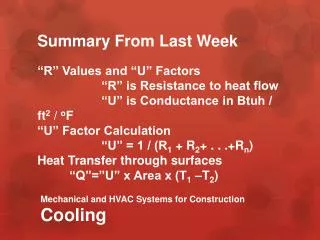
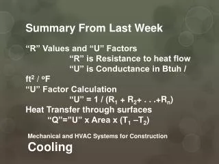
Beam Cooling. M. Steck, GSI, Darmstadt JUAS, Archamps , France March 9, 2015. Cooling. longitudinal (momentum) cooling. injection into storage ring. transverse cooling. time. Xe 54+ 50 MeV/u. p/p. cooling off. heating (spread) and energy loss (shift). cooling:

E N D
Beam Cooling M. Steck, GSI, Darmstadt JUAS, Archamps, France March 9, 2015
Cooling longitudinal (momentum) cooling injection into storage ring transverse cooling time Xe54+ 50 MeV/u p/p cooling off heating (spread) and energy loss (shift) cooling: good energy definition small beam size highest precision cooling on with internal gastarget operation Xe54+ 15 MeV/u
Beam Cooling • Introduction • Electron Cooling • Ionization Cooling • Laser Cooling • Stochastic Cooling
Beam Cooling Beam cooling is synonymous for a reduction of beam temperature Temperature is equivalent to terms as phase space volume,emittance and momentum spread Beam Cooling processes are not following Liouville‘s Theorem: `in a system where the particle motion is controlled by external conservative forces the phase space density is conserved´ (This neglect interactions between beam particles.) Beam cooling techniques are non-Liouvillean processes whichviolate the assumption of a conservative force. e.g. interaction of the beam particles with other particles (electrons, photons, matter)
Cooling Force Generic (simplest case of a) ooling Force: vx,y,s velocity in the restframe of the beam non conservative, cannot be described by a Hamiltonian For a 2D subspace distribution function cooling (damping) rate in a circular accelerator: Transverse (emittance) cooling rate Longitudinal (momentum spread) cooling rate
Beam Temperature Where does the beam temperature originate from? The beam particles are generated in a ‘hot’ source at rest (source) at low energy at high energy In a standard accelerator the beam temperature is not reduced(thermal motion is superimposed the average motion after acceleration) but: many processes can heat up the beam e.g. heating by mismatch, space charge, intrabeam scattering, internal targets, residual gas, external noise
Beam Temperature Definition Longitudinal beam temperature Transverse beam temperature Distribution function Particle beams can be anisotropic: e.g. due to laser cooling or the distribution of the electron beam Don‘t confuse: beam energy beam temperature (e.g. a beam of energy 100 GeV can have a temperature of 1 eV)
Benefits of Beam Cooling • Improved beam quality • Precision experiments • Luminosity increase • Compensation of heating • Experiments with internal target • Colliding beams • Intensity increase by accumulation • Weak beams from source can be enhanced • Secondary beams (antiprotons, rare isotopes)
1. Electron Cooling ve║ = ec= ic = vi║ Ee=me/MiEi e.g.: 220 keV electronscool 400 MeV/u ions electron temperature kBT 0.1 eV kBT║ 0.1 - 1 meV superpositionof a cold intense electron beamwith the same velocity momentum transfer by Coulomb collisions cooling force results from energy lossin the co-moving gas of free electrons
Simple Derivation of the Electron Cooling Force in reference frameof the beam electrontarget Analogy: energy loss in matter (electrons in the shell) slower ion faster ion Rutherford scattering: Energy transfer: Minimum impact parameter: db from: b Energy loss: Coulomb logarithm LC=ln (bmax/bmin) 10 (typical value)
Characteristics of the Electron Cooling Force cooling force F for small relative velocity: vrel for large relative velocity: vrel-2 increases with charge: Q2 |F| vrel |F| 1/vrel2 maximum of cooling force at effective electron temperature
Electron Cooling Time first estimate:(Budker 1967) for large relative velocities cooling time • cooling rate (-1): • slow for hot beams 3 • decreases with energy -2 ( is conserved) • linear dependence on electron beam intensity ne and cooler length =Lec/C • favorable for highly charged ions Q2/A • independent of hadron beam intensity for small relative velocities cooling rate is constant and maximum at small relative velocity F vrel = t = prel/F = constant
Models of the Electron Cooling Force • binary collision model • description of the cooling process by successive collisions of two particles • and integration over all interactions • analytic expressions become very involved, various regimes • (multitude of Coulomb logarithms) • dielectric model • interaction of the ion with a continuous electron plasma (scattering off of plasma waves) • fails for small relative velocities and high ion charge • an empiric formula (Parkhomchuk) derived from experiments:
Electron Beam Properties electron beam temperature transverse kBT = kBTcat , with transverse expansion ( Bc/Bgun) longitudinal kBT = (kBTcat)2/4E0 kBT lower limit : typical values: kBT 0.1 eV (1100 K), kBT 0.1 - 1 meV Gun electron beam confined by longitudinal magnetic field (from gun to collector) Cooling Section Collector constant electron beam radius transversely expanded electron beam radial variation of electron energy due to space charge:
Electron Motion in Longitudinal Magnetic Field single particle cyclotron motion cyclotron frequency c = eB/me cyclotron radius rc = v/c = (kBTme)1/2 /eB electrons follow the magnetic field line adiabatically important consequence: for interaction times long compared tothe cyclotron period the ion does not sense the transverseelectron temperature magnetized cooling ( Teff T║ T) electron beam space charge: transverse electric field + B-field azimuthal drift electron and ion beam should be well centered • Favorable for optimum cooling (small transverse relative velocity): • high parallelism of magnetic field lines B/B0 • large beta function (small divergence) in cooling section
EKIN Continuum bound states M L K Imperfections and Limiting Effects in Electron Cooling physical limitation: technical issues: ripple of accelerating voltage magnetic field imperfections beam misalignment space charge of electron beam and compensation Radiative Electron Capture (REC) losses by recombination (REC) loss rate
Examples of Electron Cooling measured with residual gas ionization beam profile monitor fast transverse cooling at TSR, Heidelberg transverse cooling at ESR, Darmstadt cooling of 350 MeV/u Ar18+ions 0.05 A, 192 keV electron beam ne = 0.8 ×106 cm-3 profile every 0.1 s. cooling of 6.1 MeV/u C6+ions 0.24 A, 3.4 keV electron beam ne = 1.56 ×107 cm-3 note! time scale cooling times vary
Accumulation of Heavy Ions by Electron Cooling horizontal vertical standard multiturn injection fast transverse cooling profile beam size fast accumulation by repeated multiturn injectionwith electron cooling intensity increase in 5 s by a factor of 10 limitations: space charge tune shift recombination (REC)
Accumulation of Secondary Particles basic idea: confine stored beam to a fractionof the circumference, inject into gap and apply cooling to merge the two beam componentsfast increase of intensity (for secondary beams) experimental verification at ESR Xe54+154 MeV/u time fresh injection longit. position injected beam stack stack stack beam current increase barrier voltage 2 kV simulation of longitudinal stacking with barrier bucketsand electron cooling
Examples of Electron Cooling high energy electron cooling of 8 GeV antiprotons longitudinal cooling with 0.2 A, 4.4 MeV electron beam first electron coolingat relativistic energyat Recycler, FNAL measured by detectionof longitudinal Schottky noise
Electron Cooling Systems High Energy: 4.3 MeV Recycler/FNAL Low Energy: 35 keV SIS/GSI pelletron Medium Energy: 300 keV ESR/GSI 20 m long solenoid section
Bunched Beam Electron Cooling Electron cooling with electrostatic acceleration is limited in energy (5-10 MeV). A bunched electron beam offers the extension of the electron cooling methodto higher energy (linear rf accelerator). traditional new scheme continuous electron beam ion bunch (some ten nsor continuous) electron bunches (some ns) continuous (or bunched) ion beam • Issues: • high intensity bunches (production, transport) • momentum spread and emittance of bunches • beam alignment • magnetized non-magnetized (magnetic shielding) • synchronization Low Energy RHIC e-Cooler(LEReC) project at BNL two counter-propagating ion beams super-conducting rf gun two opposite cooling sections 5 MeV, 250 kW beam dump
2. Ionization Cooling energy loss in solid matter proposed for muon cooling not useful for heavy particles due to strong interaction with matter small at absorber in order to minimize multiple scattering transverse cooling large LR, (dE/ds) light absorbers (H2)
Ionization Cooling increased longitudinal cooling by longitudinal-transverse emittance exchange cooling term heating term cooling, if x x0 + D p/p emittance exchange increased longitudinal cooling reduced transverse cooling
Scenarios with Ionization Cooling Muon Collider Neutrino Factory helical cooling channel sequence of solenoids, rf and absorbers beam path
MICE Muon Ionization Cooling Experiment at ISIS, Rutherford
3. Laser Cooling excitation with directed momentum transfer cooling force Lorentzian with width /k ~ 10 m/s minimum temperature (Doppler limit) typical 10-5 – 10-4 K typical cooling time ~ 10 s isotropic emission closed optical transition the directed excitation andisotropic emission result ina transfer of velocity vr drawback: only longitudinal cooling
Laser Cooling a single laser does not provide cooling (only acceleration or deceleration) schemesfor cooling two counter-propagating lasers(matched to beam velocity) auxiliary force(betatron core, rf) capture range of laser is limited frequency sweep (snowplow) ions studies so far: 7Li1+, 9Be1+, 24Mg1+, 12C3+ in future: Li-like heavy ions at relativistic energies large relativistic energy large excitation energy in PRF
Laser Cooling of C3+ at the ESR Argon ion laser(257.3 nm) frequency doubled Schottky noiseduring rf sweep fluorescence light detection
4. Stochastic Cooling First cooling method which was successfully used for beam preparation S. van der Meer, D. Möhl, L. Thorndahl et al. (1925 – 2011) (1936-2012) Conditions: Betatron motion phase advance (pick-up to kicker): (n + ½) Signal travel time = time of flight of particle(between pick-up and kicker) Sampling of sub-ensemble of total beam pick-up kicker amplifier kick deviation Principle of transverse cooling: measurement of deviation from ideal orbit is used for correction kick (feedback)
Stochastic Cooling single particle betatron motionalong storage ring without and with correction kick projection to two-dimensionalhorizontal phase area kick1 kick2 kick3=0
Stochastic Cooling correction kick (unlimited resolution) correction kick Nyquist theorem: a system with a band-width f = W in frequency domain can resolve a minimum time duration T=1/(2W) correction kick Correction kick For exponential damping (x(t)=x(t0) exp(-(t-t0)/)): coolingrate
Stochastic Cooling some refinements of cooling rate formula noise:thermal or electronic noise adds to beam signal mixing:change of relative longitudinal position of particles due to momentum spread M mixing factor U noise to signal ratio cooling rate coolingheating maximum of cooling rate further refinement (wanted unwanted mixing): (kicker to pick-up) (pick-up to kicker) with wanted mixing and unwanted mixing
Stochastic Cooling Circuit goals: high gain large bandwidth low noise typical band-width: 1, 2, 4 GHz (range 1-2, 2-4, 4-8 GHz) for 108 antiprotons and W = 1 GHz cooling time N/2W = 0.05 s realistic: 1 s noise Transfer Function:
Longitudinal Stochastic Cooling 1) Palmer cooling pick-up in dispersive section detects horizontal position acceleration/deceleration kick corrects momentum deviation 2) Notch filter cooling filter creates notches at the harmonics of the nominal revolution frequency particles are forced to circulate at the nominal frequency notches at harmonics of the revolution frequency with 180º phase jump transmission line short circuit at all harmonicsof the revolution frequency
Antiproton Accumulationby Stochastic Cooling accumulation of 8 GeV antiprotons at Accumulator, FNAL, shut down 09/2011 similar facility AC/AA at CERN, shut down 11/1996 kicker array cryogenic microwave amplifier momentum distribution of accumulatedantiproton beam power amplifiers (TWTs) microwave electronics
Stochastic Cooling of Rare Isotopes at GSI fast pre-cooling of hot fragment beams electrodes installed inside magnets energy 400 (-550) MeV/ubandwidth 0.8 GHz (range 0.9-1.7 GHz) p/p = 0.35 % p/p = 0.01 %e = 10 10-6m e = 2 10-6m combination of signals from electrodes power amplifiersfor generation ofcorrection kicks
E < Eh Eh E < Eh Dispersion section ( for hadrons) E > Eh Eh Hadrons Kicker Modulator E > Eh l1 High gain FEL (for electrons) l2 Electrons Coherent ElectronCooling A combination of electron and stochastic cooling concepts proposed for fast cooling at highest energiesenergy range several 10 – 100 GeV • The Coherent Electron Cooling system has three major subsystems • modulator: the ions imprint a “density bump” on the electron distribution • amplifier: FEL interaction amplifies a density bump by orders of magnitude • kicker: the amplified & phase-shifted electron charge distribution is used to correct the velocity offset of the ions
Comparison of Cooling Methods Stochastic CoolingElectron Cooling Useful for: low intensity beams low energy all intensities hot (secondary) beams warm beams (pre-cooled) high charge high charge full 3 D control bunched beams Limitations: high intensity beams space charge effects /problems beam quality limited recombination losses bunched beams high energy laser cooling (of incompletely ionized ions) and ionization cooling (of muons) are quite particular and not general cooling methods
Trends in Beam Cooling Stochastic cooling was mainly developed for the production of highintensity antiproton beams for colliders (CERN, FNAL, 1972 – 2011). It is still in operation at AD (CERN), COSY (FZJ) and ESR (GSI). It will also be used in the FAIR project (Germany) for cooling of antiprotons andrare isotope beams. First demonstration of bunched beam stochastic cooling (2008) withions (BNL) made it also attractive for ion colliders.Now it is proposed for the collider of the Russian NICA project. Electron cooling was and still is used in low energy storage ringsfor protons, ions, secondary beams (antiprotons, rare isotopes). Electron cooling is interesting for low energy storage rings, but alsoapplication at higher energies (MeV electron energies) is envisaged after the successful demonstration of the 4 MeV electron cooler at FNAL. Other cooling methods, like muon (ionization) cooling or coherent electroncooling are under investigation, but are still far from implementation in a full scale machine.
References 1 (general) Y. Zhang, W. Chou (editors), ICFA Beam Dynamics Newsletter No. 64 A. Chao, M. Tigner, Handbook of Accelerator Physics and Engineering,Chapter 2.8, World Scientific, Singapore, 1999 M. Minty, F. Zimmermann, Measurement and Control of ChargedParticle Beams, Chapter 11, Springer Verlag, Berlin, 2003 D. Möhl, Principle and Technology of Beam Cooling, CERN/PS 86-31,1986 D. Möhl, Beam Cooling, CAS 2005, CERN 2005-04, pp.324-339 H. Danared, Beam Cooling CAS 2005, CERN 2005-06, pp. 343-362
References 2 (specialized) Electron Cooling: H. Poth, Electron Cooling, CAS 85, CERN 87-03, pp. 534-569, 1987 H. Poth, Electron Cooling: Theory, Experiment, Application,Phys. Rep. Vol. 196 Issues 3-4, pp. 135-297, 1990 I. Meshkov, Electron Cooling: Status and Perspectives, Physics of Particles and Nuclei, Vol. 25, Issue 6, pp. 631-661, 1994 Stochastic Cooling: D. Möhl, Stochastic Cooling for Beginners, CAS 1983, CERN 84-15, pp. 97-162 D. Möhl, Stochastic Cooling, CAS 85, CERN 87-03, pp. 453-533, 1987 D. Möhl, Stochastic Cooling of Particle Beams, Springer Lecture Notes in Physics 866 (2013) S. van der Meer, Rev. Mod. Phys. Vol. 57, No. 3 Part 1, 1985 Laser Cooling: E. Bonderup, Laser Cooling, CAS 1993, CERN 95-06, pp. 731-748 Ionization Cooling: D. Neuffer, Introduction to Muon Cooling, Nucl. Instr. Meth. A 532 (2004) 26-31 Biannual Workshops on Beam Cooling: e. g. COOL’15, Jefferson Lab, USA