Download

1 / 49
530 likes | 1.36k Views
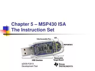
Chapter 5 – MSP430 ISA The Instruction Set. The “Gap”. Where Are We?. Problems. Algorithms. Language (Program). Programmable. Computer Specific. Machine (ISA) Architecture. Micro-architecture. Manufacturer Specific. Circuits. Devices. MSP430 ISA. Instruction Set Architecture.

E N D
The “Gap” Where Are We? Problems Algorithms Language (Program) Programmable Computer Specific Machine (ISA) Architecture Micro-architecture Manufacturer Specific Circuits Devices Chapter 05 - MSP430 ISA
MSP430 ISA Instruction Set Architecture • The computer ISA defines all of the programmer-visible components and operations of the computer • memory organization • address space -- how may locations can be addressed? • addressibility -- how many bits per location? • register set • how many? what size? how are they used? • instruction set • opcodes • data types • addressing modes • ISA provides all information needed for someone that wants to write a program in machine language(or translate from a high-level language to machine language). Chapter 05 - MSP430 ISA
MSP430 Instruction Set Architecture Implements RISC architecture with 27 instructions and 7 addressing modes. Orthogonal architecture with every instruction usable with every addressing mode. Sixteen 16-bit registers Single-cycle register operations. Reduces fetches to memory. Full access to program counter, status register, and stack pointer. 16-bit address bus (address space) allows direct access and branching throughout entire 64KB memory range. 16-bit, byte addressable (addressability) data bus allows direct manipulation of word-wide arguments. Word and byte addressing and instruction formats. MSP430 ISA Chapter 05 - MSP430 ISA
MSP430 Registers R0 (PC) – Program Counter This register always points to the next instruction to be fetched Each instruction occupies an even number of bytes. Therefore, the least significant bit (LSB) of the PC register is always zero. After fetch of an instruction, the PC register is incremented by 2, 4, or 6 to point to the next instruction. R1 (SP) – Stack Pointer The MSP430 CPU stores the return address of routines or interrupts on the stack User programs store local data on the stack The SP can be incremented or decremented automatically with each stack access The stack “grows down” thru RAM and thus SP must be initialized with a valid RAM address SP always points to an even address, so its LSB is always zero MSP430 ISA Chapter 05 - MSP430 ISA
MSP430 Registers R2 (SR/CG1) – Status Register The status of the MSP430 CPU is contained in register R2 Only accessable through register addressing mode - all other addressing modes are reserved to support the constants generator V Overflow bit SCG1 Turns off the SMCLK. Register As Constant Remarks SCG0 Turns off the DCO dc generator. R2 00 - Register mode R2 01 (0) Absolute mode OSCOFF Oscillator off R2 10 00004h +4, bit processing CPUOFF Turns off the CPU. R2 11 00008h +8, bit processing GIE General interrupt enable R3 00 00000h 0, word processing R3 01 00001h +1 N Negative bit R3 10 00002h +2, bit processing Z Zero bit R3 11 0FFFFh -1, word processing C Carry bit MSP430 ISA • R3 (CG2) – Constant Generator • R4-R15 – General Purpose registers Chapter 05 - MSP430 ISA
16 bit Arithmetic Logic Unit (ALU). Performs instruction arithmetic and logical operations Instruction execution affects the state of the following flags: Zero (Z) Carry (C) Overflow (V) Negative (N) The MCLK (Master) clock signal drives the CPU. MSP430 ALU MSP430 ISA Chapter 05 - MSP430 ISA
MSP430 Memory Organization MSP430 ISA BYU CS/ECEn 124 Chapter 05 - MSP430 ISA Chapter 6 - MSP430 Micro-Architecture 8
MSP430 Instructions There are three formats used to encode instructions for processing by the CPU core Double operand Single operand Jumps The instructions for double and single operands, depend on the suffix used, (.W) word or (.B) byte These suffixes allow word or byte data access If the suffix is ignored, the instruction processes word data by default Instruction Formats Chapter 05 - MSP430 ISA
MSP430 Instructions PC 0000 Op-code 0001 0010 0011 0100 0101 0110 0111 4 to 16 Decoder 1000 1001 1010 1011 1100 1101 1110 1111 Instruction Formats Instruction Register Chapter 05 - MSP430 ISA
MPS430 Instruction Formats Format I: Instructions with two operands: MSP430 Instructions • Format II: Instruction with one operand: • Format III: Jump instructions: Chapter 05 - MSP430 ISA
Format I: Double Operand Double operand instructions: Double Operand Instructions Chapter 05 - MSP430 ISA
Example: Double Operand Copy the contents of a register to another register Assembly: mov.w r5,r4 Instruction code: 0x4504 One word instruction The instruction instructs the CPU to copy the 16-bit 2’s complement number in register r5 to register r4 Double Operand Instructions Chapter 05 - MSP430 ISA
Format II: Single Operand Single operand instructions: Single Operand Instructions Chapter 05 - MSP430 ISA
Example: Single Operand Logically shift the contents of register r5 to the right through the status register carry Assembly: rrc.w r5 Instruction code: 0x1005 One word instruction The CPU shifts the 16-bit register r5 one bit to the right (divide by 2) – the carry bit prior to the instruction becomes the MSB of the result while the LSB shifted out replaces the carry bit in the status register Single Operand Instructions Chapter 05 - MSP430 ISA
Jump Instruction Format Jump instructions are used to direct program flow to another part of the program. The condition on which a jump occurs depends on the Condition field consisting of 3 bits: 000: jump if not equal 001: jump if equal 010: jump if carry flag equal to zero 011: jump if carry flag equal to one 100: jump if negative (N = 1) 101: jump if greater than or equal (N = V) 110: jump if lower (N V) 111: unconditional jump Jump Instructions Chapter 05 - MSP430 ISA
Jump Instruction Format Jump instructions are executed based on the current PC and the status register Conditional jumps are controlled by the status bits Status bits are not changed by a jump instruction The jump off-set is represented by the 10-bit, 2’s complement value: Thus, the range of the jump is -511 to +512 words, (-1023 to 1024 bytes ) from the current instruction Note: Use a BR instruction to jump to any address Jump Instructions Chapter 05 - MSP430 ISA
Example: Jump Format Continue execution at the label main if the carry bit is set Assembly: jc main Instruction code: 0x2fe4 One word instruction The CPU will add to the PC (R0) the value -28 x 2 if the carry is set Jump Instructions Chapter 05 - MSP430 ISA
Source Addressing Modes The MSP430 has four basic modes for the source address: Rs - Register x(Rs) - Indexed Register @Rs - Register Indirect @Rs+ - Indirect Auto-increment In combination with registers R0-R3, three additional source addressing modes are available: label - PC Relative, x(PC) &label – Absolute, x(SR) #n – Immediate, @PC+ Addressing Modes Chapter 05 - MSP430 ISA
Destination Addressing Modes There are two basic modes for the destination address: Rd - Register x(Rd) - Indexed Register In combination with registers R0/R2, two additional destination addressing modes are available: label - PC Relative, x(PC) &label – Absolute, x(SR) Addressing Modes Chapter 05 - MSP430 ISA
Register Mode (Rn) The operand is contained in one of the MSP430 registers (R0 to R15) Available for source and/or destination operands The register is specified in the instruction; no further data is needed The fastest mode and does not require an addition cycle Byte instructions use only the lower byte, but clear the upper byte when writing to a register Example ; add the contents of R7 to the contents of R8 ; add r7,r8 ; r7 + r8 r8 Addressing Modes Chapter 05 - MSP430 ISA
Indexed Mode x(Rn) The address of the operand is the sum of the index and the contents of the specified register The index is contained in the word following the instruction and requires an additional memory cycle Excludes registers R0, R2, and R3 (used for other addressing modes) Indexed addressing can be used for source and/or destination There is no restriction on the address when accessing a byte, but word accesses must lie on an even addresses Example ; compare 2nd byte of table with byte in R15 ; cmp.b 1(r6),r15 ; r15 - M(1 + r6) Addressing Modes Chapter 05 - MSP430 ISA
Symbolic Mode (PC Relative) The address of the operand is formed by adding a constant (index) to the program counter (PC) The index is contained in the word following the instruction and requires an additional memory cycle Symbolic addressing can be used for source and/or destination Produces position-independent code Note: this is NOT an appropriate mode of addressing when referencing fixed locations in memory such as the special function registers (SFR’s) – use absolute addressing mode Example ; add the ROM word EDE to the RAM word TONI ; add EDE,TONI ; M(EDE)+M(TONI)M(TONI) Addressing Modes Chapter 05 - MSP430 ISA
Absolute Mode (&label) The address of the operand is a constant (index) and specified by preceding a label with an ampersand (&) The absolute memory address is stored in the memory word following the instruction and requires an additional cycle Absolute addressing mode is a special case of indexed addressing mode using the status register SR as the base register (the status register R2 always contains a zero in this case) Note: this is the preferred mode of addressing when referencing fixed locations in memory such as the special function registers (SFR’s) Example ; move memory word cnt to register R6 ; mov.w &cnt,r6 ; M(cnt) r6 Addressing Modes Chapter 05 - MSP430 ISA
Indirect Register Mode (@Rn) The address of the operand is in the specified register Only available for source operands The operand can be located anywhere in the 64K address space Same as indexed mode with index equal to 0, but does not require an additional instruction word The value of the indirect register is unchanged Example ; add byte addressed by R5 to the contents of R6 ; add.b @r5,r6 ; M(r5) + r6 r6 Addressing Modes Chapter 05 - MSP430 ISA
Indirect Auto-increment Mode (@Rn+) The address of the operand is in the specified register; after the operand is fetched, the register is automatically incremented by 1 (byte) or 2 (word) Only available for source operands. Usually called post-increment addressing. Note: All operations on the first operand are fully completed before the second operand is evaluated Example ; copy the byte addressed by r8 to r9 ; afterwards increment r8 ; mov.b @r8+,r9 ; M(r8) r9; r8+1 r8 Addressing Modes Chapter 05 - MSP430 ISA
Immediate Mode (#n) The operand is an immediate value The immediate value is stored in the memory word following the instruction and requires an additional cycle Only available for source operands Special case of auto-increment addressing using the program counter (PC) as the source register The PC is automatically incremented after the instruction word is fetched; hence points to the immediate value Example ; move the constant 100 to R6 ; mov.w #100,r6 ; 100 r6 Addressing Modes Chapter 05 - MSP430 ISA
“Where is my mail?” Quiz Quiz Match the addressing modes to the right with the analogous mail locations to the left. Chapter 05 - MSP430 ISA
Quiz Quiz • How many basic source addressing modes are defined by the MSP430 ISA? • When used in combination with registers R0-R3, how many additional source addressing modes are defined by the MSP430 ISA? • How many basic destination addressing modes are defined by the MSP430 ISA? • When used in combination with registers R0-R3, how many additional destination addressing modes are defined by the MSP430 ISA? Chapter 05 - MSP430 ISA
Review Examples… Chapter 05 - MSP430 ISA
Double Operand Instructions Data Instructions Status Register: • = bit affected, – = bit not affected, 0 = cleared, 1 = set, z = same as Z • The MOV instruction replaces the destination operand with a copy the source operand. • NOTE: The status register is not affected by this instruction • The CMP instruction internally subtracts the source operand from the destination operand, updates the status register bits, and then discards the results of the subtraction. Chapter 05 - MSP430 ISA
Double Operand Instructions Arithmetic Instructions Status Register: • = bit affected, – = bit not affected, 0 = cleared, 1 = set, z = same as Z • The ADD, ADDC, SUBC, SUB, and DADD instructions replaces the destination operand with the results of the source operand operating on the destination operand. • The V, N, Z, and C bits in the status register are set/reset depending upon the result of the operation. Chapter 05 - MSP430 ISA
Double Operand Instructions Logical Instructions Status Register: • = bit affected, – = bit not affected, 0 = cleared, 1 = set, z = same as Z • The BIT, BIC, BIS, XOR, and AND instructions replaces the destination operand with the results of the source operand operating on the destination operand. • These are bit-wise, logical instructions • The BIC and BIS do not affect the status register. Chapter 05 - MSP430 ISA
Single Operand Instructions Logical Register Instructions Status Register: • = bit affected, – = bit not affected, 0 = cleared, 1 = set, z = same as Z • The RCC, SWPB, RRA, and SXT instructions operate on a single. • These are bit-wise, logical instructions. • The BIC and BIS do not affect the status register. • The PUSH instruction decrement the stack pointer by 2 and stores the operand on the stack using the indirect addressing mode. Chapter 05 - MSP430 ISA
Single Operand Instructions Program Flow Control Instructions Status Register: • = bit affected, – = bit not affected, 0 = cleared, 1 = set, z = same as Z • The CALL instruction pushes the program counter (R0) on the stack and them moves the operand to the program register. • CALL is used to link to a subroutine. • A return from subroutine is performed by moving the top of the stack into the program counter. • The CALL instruction does not affect the status register. • The RETI instruction “pops” a status register (R2) and program counter (R0) from the stack. Chapter 05 - MSP430 ISA
Jump Instructions Jump Instructions Status Register: • = bit affected, – = bit not affected, 0 = cleared, 1 = set, z = same as Z • The jump instructions support branching relative to the PC and do not affect the status bits. • PCnew = PCold + 2 + PCoffset 2 • The possible range is -511 to +512 words relative to the PC value at the jump instruction. Chapter 05 - MSP430 ISA
Quiz… Disassemble the following MSP430 instructions: Quiz AddressData 0x8010: 4031 0x8012: 0600 0x8014: 40B2 0x8016: 5A1E 0x8018: 0120 0x801a: 430E 0x801c: 535E 0x801e: F07E 0x8020: 000F 0x8022: 1230 0x8024: 000E 0x8026: 8391 0x8028: 0000 0x802a: 23FD 0x802c: 413F 0x802e: 3FF6 Chapter 05 - MSP430 ISA
Emulated Instructions In addition to the 27 instructions defined by the MSP 430 ISA, there are 24 additional emulated instructions The emulated instructions make reading and writing code more easy, but do not have their own op-codes Emulated instructions are replaced automatically by native MSP 430 instructions There are no penalties for using emulated instructions. Emulated Instructions Chapter 05 - MSP430 ISA
Emulated Instructions Emulated Instructions Chapter 05 - MSP430 ISA
Emulated Instructions Emulated Instructions Chapter 05 - MSP430 ISA
Emulated Instructions Emulated Instructions Chapter 05 - MSP430 ISA
Example: Emulated Instructions Clear the contents of register R5: Instruction code: 0x4305 This instruction is equivalent to MOV R3,R5, where R3 takes the value #0. Emulated Instructions CLR R5 Chapter 05 - MSP430 ISA
Example: Emulated Instructions Increment the content of register R5: Instruction code: 0x5315 This instruction is equivalent to ADD 0(R3),R5 where R3 takes the value #1. Emulated Instructions INC R5 Chapter 05 - MSP430 ISA
Example: Emulated Instructions Decrement the contents of register R5: Instruction code: 0x8315 This instruction is equivalent to SUB 0(R3),R5 where R3 takes the value #1. Emulated Instructions DEC R5 Chapter 05 - MSP430 ISA
Example: Emulated Instructions Decrement by two the contents of register R5: Instruction code: 0x8325 This instruction is equivalent to SUB @R3,R5, where R3 points to the value #2. Emulated Instructions DECD R5 Chapter 05 - MSP430 ISA
Example: Emulated Instructions Do not carry out any operation: Instruction code: 0x4303 This instruction is equivalent to MOV R3,R3 and therefore the contents of R3 are moved to itself. Emulated Instructions NOP Chapter 05 - MSP430 ISA
Example: Emulated Instructions Add the carry flag to the register R5: Instruction code: 0x6305 This instruction is equivalent to ADDC R3,R5, where R3 takes the value #0. Emulated Instructions ADC R5 Chapter 05 - MSP430 ISA