Download
1 / 19
1.87k likes | 4.26k Views
Gears. Applications of Gears. Toys and Small Mechanisms – small, low load, low cost kinematic analysis. Appliance gears – long life, low noise & cost, low to moderate load kinematic & some stress analysis. Power transmission – long life, high load and speed

E N D
Gears Mechanical Engineering Dept.
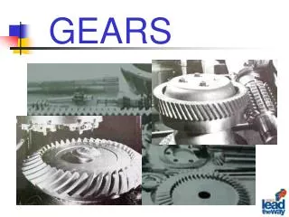
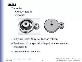
Applications of Gears • Toys and Small Mechanisms– small, low load, low cost • kinematic analysis • Appliance gears– long life, low noise & cost, low to moderate load • kinematic & some stress analysis • Power transmission– long life, high load and speed • kinematic & stress analysis • Aerospace gears– light weight, moderate to high load • kinematic & stress analysis • Control gears– long life, low noise, precision gears • kinematic & stress analysis Mechanical Engineering Dept.
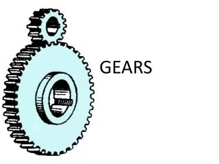
Internal gears – teeth are inclined to the axis of rotation, the angle provides more gradual engagement of the teeth during meshing, transmits motion between parallel shafts. Helical gears Gear (large gear) Types of Gears Spur gears– tooth profile is parallel to the axis of rotation, transmits motion between parallel shafts. Pinion (small gear) Mechanical Engineering Dept.
Straight bevel gear Spiral bevel gear Types of Gears Bevel gears– teeth are formed on a conical surface, used to transfer motion between non-parallel and intersecting shafts. Mechanical Engineering Dept.
Rack and Pinion sets– a special case of spur gears with the gear having an infinitely large diameter, the teeth are laid flat. Pinion Rack Types of Gears Worm gear sets– consists of a helical gear and a power screw (worm), used to transfer motion between non-parallel and non-intersecting shafts. Mechanical Engineering Dept.
Gear Design and Analysis • Kinematics of gear teeth and gear trains. • Force analysis. • Design based on tooth bending strength. • Design based on tooth surface strength. Mechanical Engineering Dept.
Base Circle Pitch circle gear diam. Backlash = (tooth spacing)driven gear – (tooth thickness)driver , measured on the pitch circle. Nomenclature of Spur Gear Teeth Clearance Fillet radius Mechanical Engineering Dept.
rG rP Generation of the involute curve All common normals have to intersect at the same point P rG / rP = constant (constant speed ratio) Fundamental Law and Involute Curve Tangent at the point of contact Mechanical Engineering Dept.
p (circular pitch) = πd / N Pp = π Metric system m (module, mm) = d / N Useful Relations P = N / d P = diametral pitch, teeth per inch N = number of teeth d = pitch diameter (gear diameter) Mechanical Engineering Dept.
Base circle Pressure angle φ Pitch circle Pitch circle Base circle Standard pressure angles, 14.5o (old), 20o, and 25o Pressure angle Standard Tooth Specifications Line of action Pitch line Line of centers Two mating gears must have the same diametral pitch, P, and pressure angle, φ. Mechanical Engineering Dept.
Standard Tooth Specifications Power transmission, 2 ≤ P ≤ 16 Mechanical Engineering Dept.
ωp dp dg ωg Rack and pinion Displacement of the rack Δθ is in radians , Velocity of the rack Kinematics Spur, helical and bevel gears P = (Ng / dg) = (Np / dp) (ωp / ωg) = (dg / dp) = (Ng / Np) = VR (velocity ratio) Mechanical Engineering Dept.
Kinematics Worm Gear Sets Ng = number of teeth on the helical gear Helical gear Nw = number of threads on the worm, usually between 2-6 Speed ratio = Ng / Nw Worm Large reduction in one step, but lower efficiency due heat generation. Mechanical Engineering Dept.
ω3 ω5 N4 N2 = = ω4 ω2 , N3 N5 , ω3 ω4 = Speed ratio ω5 output ω2 = = input mV = e = train value Reverted gear train – output shaft is concentric with the input shaft. Center distances of the stages must be equal. Kinematics of Gear Trains Conventional gear trains Mechanical Engineering Dept.
= e (train value) Planetary gear trains Kinematics of Gear Trains gear =arm + gear/arm F/arm =F - arm , L/arm = L - arm Mechanical Engineering Dept.
Kinematics of Gear Trains Determine the speed of the sun gear if the arm rotates at 1 rpm. Ring gear is stationary. 2 degrees of freedom, two inputs are needed to control the system Mechanical Engineering Dept.
Planetary Gear Trains - Example For the speed reducer shown, the input shaft a is in line with output shaft b. The tooth numbers are N2=24, N3=18, N5=22, and N6=64. Find the ratio of the output speed to the input speed. Will both shafts rotate in the same direction? Gear 6 is a fixed internal gear. Train value = (-N2 / N3)(N5 / N6) = (-24/18)(22/64) = -.4583 -.4583 = (ωL – ωarm) / (ωF – ωarm) = (0 – ωarm) / (1 – ωarm) ωarm = .125, reduction is 8 to 1 Input and output shafts rotate in the same direction d2 + d3 = d6 – d5 Mechanical Engineering Dept.
Wave Generator Consists of a steel disk and a specially design bearing. The outer surface has an elliptical shape. The ball bearing conforms to the same elliptical shape of the wave generator. The wave generator is usually the input. Flexspline The Flexspline is a thin-walled steel cup with gear teeth on the outer surface near the open end of the cup. Flexspline is usually the output. Circular Spline Rigid internal circular gear, meshes with the external teeth on the Flexspline. The mechanism is comprised of three components: Wave Generator, Flexspline, and Circular Spline. Harmonic Drive Mechanical Engineering Dept.
The flexspline has two less teeth than the circular spline. Gear Ratio = - (Nflex spline)/ 2 ωWave Generator= input ω Flexspline= output ω Circular Spline= 0 , , Harmonic Drive Teeth on the Flexspline and circular spline simultaneously mesh at two locations which are 180o apart. As the wave generator travels 180o, the flexspline shifts one tooth with respect to circular spline in the opposite direction. Mechanical Engineering Dept.