Download
1 / 20
200 likes | 344 Views
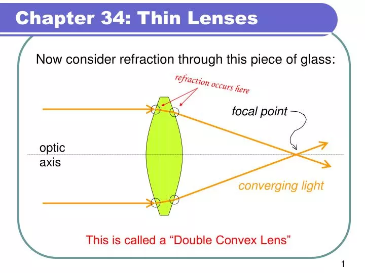
refraction occurs here. Now consider refraction through this piece of glass:. focal point. optic axis. converging light. This is called a “Double Convex Lens”. Converging Lenses (convex) Diverging Lenses (concave). Don’t confuse these reflections for something meaningful.

E N D
refraction occurs here Now consider refraction through this piece of glass: focal point optic axis converging light This is called a “Double Convex Lens”
Converging Lenses (convex) Diverging Lenses (concave)
Don’t confuse these reflections for something meaningful. Diverging Lens Where is the focal point for these 4 incoming rays? Converging Lens The focal point is visible because real rays go through it.
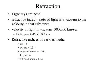
Optical Ray Diagram: a line drawing depicting a small number of key light rays. For a lens, an optical ray diagram should include: • Parallel Ray.A ray parallel to the optic axis which passes through the object & the focal point. • Focal Ray. A ray that passes through both the focal point and the object. • Chief Ray. A ray that passes through both the center of the lens and the object. These three rays intersect at the image. Note: we don’t use reflected rays in lens analysis.
The Diverging Lens real part parallel ray f f Virtual part: where the refracted ray appears to come from. virtual part
The Diverging Lens focal ray real part virtual part Virtual part: where the refracted ray appears to come from.
The Diverging Lens chief ray The chief ray has no virtual part.
Put all three rays together: The three refracted rays have no intersection.
Put all three rays together: object focal point upright image There is an intersection of the virtual parts. Need virtual parts to find the image? Virtual image.
The Thin Lens Equation Parallel ray a converging lens Chief ray Focal ray f so si
Opposite for mirrors The Thin Lens Equation Parallel ray a converging lens Chief ray Focal ray Positive side for object distance Negative side for image distance focal length (e.g. diverging lens) Positive side for image distance focal length
The Thin Lens Equation “Strength” or “Power” of lens Note: our book uses “P”. Other books use “S”. f, soand di all must have the same length units. Units of P usually in [m-1] or rather [Diopters].
Why is 1/f called the “lens power”? (or sometimes “strength”) focal point at “approaches”
Why is 1/f called the “lens power”? (or sometimes “strength”) focal point very close to the lens “approaches”
Example 1: A lens focuses light from an object 2.75m away as an image 0.483m on the other side of the lens. What are the focal length, lens type and image type? The lens is converging because: f>0 Converging lens: f>0 Diverging lens: f<0 What is the image type?
The image is real (si>0). Is it inverted or upright? 2.75 m 0.483m 6 cm = 1m 0.411m Ray diagram shows the image is: Real Inverted True whenever the object is outside the focal point of a converging lens.
Magnification: The ray diagram also shows the image is small. positive side for di and f negative side for di and f ho hi Minus sign indicates that real images are always inverted.
How to do lens problems graphically • Use a full sheet – Landscape. • Sketch the lens on the optic axis. • Sketch the objects – correctly positioned. • Show a scale. You might wish to show a different scale for vertical and horizontal lengths • Sketch two principle rays per object and find the image. • 6. Refraction occurs on the vertical center-line.
si >0 Example 2: How far from a converging lens with a focal length of 25 cm should an object be placed to produce a real image which is the same size as the object? (Minus because all real images are inverted.)
How to make a magnifying glass What kind of lens has an upright image with m>1? • si negative • |si| > |so| image is farther from the lens than the object si <0 f Place the object within the focal length of a converging lens.