Download
1 / 31
310 likes | 499 Views
GBT Project. Paulo Moreira November 2010 CERN. Outline . GBT Project Status: GBT project overview Radiation hard link GBT link bandwidth The GBT chipset The GBTIA The GBLD The GBT - SCA The GBT Protocol on FPGAs The E – Links: SLVS data transmission tests Driver/Receiver

E N D
GBT Project Paulo Moreira November 2010 CERN
Outline GBT Project Status: • GBT project overview • Radiation hard link • GBT link bandwidth • The GBT chipset • The GBTIA • The GBLD • The GBT - SCA • The GBT Protocol on FPGAs • The E – Links: • SLVS data transmission tests • Driver/Receiver • The GBT – SerDes • The GBT – SerDes Architecture • Serializer • De-serializer • Phase-Shifter • Logic • Power consumption • GBT Project Schedule • GLIB overview Paulo.Moreira@cern.ch
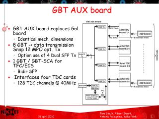
Radiation Hard Optical Link Architecture Defined in the “DG White Paper” • “Work Package 3-1” • Objective: • Development of an high speed bidirectional radiation hard optical link • Deliverable: • Tested and qualified radiation hard optical link • Duration: • 4 years (2008 – 2011) Radiation Hard Optical Link: • Versatile link project: • Opto-electronics components • Radiation hardness • Functionality testing • GBT project: • ASIC design • Verification • Radiation hardness • Functionality testing GBT GBT Versatile Link FPGA Timing & Trigger Timing & Trigger GBTX PD GBTIA DAQ DAQ LD GBLD Slow Control Slow Control Custom ASICs On-Detector Radiation Hard Electronics Off-Detector Commercial Off-The-Shelf (COTS) Paulo.Moreira@cern.ch
GBT Link Bandwidth • Bandwidth: • User: 3.36 Gb/s • Line: 4.8 Gb/s • Generic data field: • 3.2 Gb/s (80-bits) • Dedicated channels: • Link control: 80 Mb/s (2-bits) • Slow control channel: 80 Mb/s (2-bits) • DC balance: • Scrambler • No bandwidth penalty • Link is bidirectional • Link is symmetrical • Down-link highly flexible: • Can convey unique data to each frontend device that it is serving • “Soft” architecture managed at the control room level • Frame Synchronization: • Redundant header • Forward Error Correction: • Interleaved Reed-Solomon double error correction • 4-bit symbols (RS(15,11)) • Interleaving: 2 • Error correction capability: • 2 Interleaving × 2 RS = 4 symbols 16-bits • Code efficiency: 88/120 = 73% • Transmission protocol easily implemented in modern FPGAs Paulo.Moreira@cern.ch
The GBT Chipset • Radiation tolerant chipset: • GBTIA: Transimpedance optical receiver • GBLD: Laser driver • GBTX: Data and Timing Transceiver • GBT-SCA: Slow control ASIC • Supports: • Bidirectional data transmission • Bandwidth: • Line rate: 4.8 Gb/s • Effective: 3.36 Gb/s • The target applications are: • Data readout • TTC • Slow control and monitoring links. • Radiation tolerance: • Total dose • Single Event Upsets GBTIA Data<119:0> Clock<7:0> GBTX Frontend Electronics GBLD GBT-SCA Control<N:0> Paulo.Moreira@cern.ch
The GBTIA Main specs: • Bit rate 5 Gb/s (min) • Sensitivity: 20 μA P-P (10-12 BER) • Total jitter: < 40 ps P-P • Input overload: 1.6 mA (max) • Dark current: 0 to 1 mA • Supply voltage: 2.5 V • Power consumption: 250 mW • Die size: 0.75 mm × 1.25 mm Engineers : • Ping Gui – SMU, USA • Mohsine Menouni – CPPM, France Status: • Chip fabricated and tested • Chip fully meets specifications! • Radiation tolerance proven! • GBTIA + PIN-diode encapsulated in a TO Package (Versatile link project) Future: • Version 2 will address productivity • Pad positions reworked to facilitate the wire bond operation between the package and ASIC • Mean optical power monitoring to facilitate pin-diode/fiber alignment • 2.5 V supply • Migration from the LM to the DM technologies flavor Paulo.Moreira@cern.ch
The GBLD Main specs: • Bit rate 5 Gb/s (min) • Modulation: • current sink • Single-ended/differential • Laser modulation current: 2 to 12 mA • Laser bias: 2 to 43 mA • “Equalization” • Pre-emphasis/de-emphasis • Independently programmable forrising/falling edges • Supply voltage: 2.5 V • Die size: 2 mm × 2 mm • I2C programming interface Engineers : • Gianni Mazza – INFN, Italy • Angelo Rivetti – INFN, Italy • Ken Wyllie – CERN • Ping Gui – SMU, USA Status: • Chip fabricated and tested • Chip fully functional • Performance according to specs (if correctedfor the large input capacitance of the input protection diode) Future: • Reduce the area of the input protection diode Paulo.Moreira@cern.ch
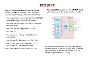
The GBT – SCA GBT-SCA Main specs: • Dedicated to slow control functions • Interfaces with the GBTX using a dedicated E-link port • Communicates with the control room using a protocol carried (transparently) by the GBT • Implements multiple protocol busses and functions: • I2C, JTAG, Single-wire, parallel-port, etc… • Implements environment monitoring functions: • Temperature sensing • Multi-channel ADC • Multi-channel DAC Engineers: • Alessandro Gabrielli – INFN, Italy • Kostas Kloukinas – CERN, Switzerland • Sandro Bonacini – CERN, Switzerland • Alessandro Marchioro – CERN, Switzerland • Filipe Sousa – CERN, Switzerland Status • Specification work undergoing: • 1st Draft already available • RTL design undergoing • Tape-out: 2011 • 10-bit ADC prototype submitted for fabrication in April 2010 Paulo.Moreira@cern.ch
The GBT Protocol on FPGAs • GBT-SERDES successfully implemented in FPGAs: • Scrambler/ Descrambler + Encoder/ Decoder + Serializer/CDR • FPGA Tested: • XILINX Virtex-5FXT and 6LXT • ALTERA Stratix II and IV GX • Optimization studies: • Optimization of use of resources (2009) • Low and “deterministic” latency (2010) • Firmware: • “Starter Kit” is available for download with various resources optimization schemes for • StratixIIGx and Virtex5FXT • Available soon for: • StratixIVGx and Virtex6LXT • Low latency • Engineers: • Sophie Baron – CERN, Switzerland • Jean-Pierre Cachemiche – CPPM, France • Csaba Soos – CERN, Switzerland • Steffen Muschter - Stockholm University • Users: • 30 registered users from all over the world (most users from collaborating institutes) • LHC experiments, but also CLIC, PANDA, GBT • Very active users are now part of the development team Xilinx - 4.8 Gb/s Altera + opto TRx - 4.8 Gb/s Paulo.Moreira@cern.ch
SLVS Driver/Receiver • Receiver • Power Supply: 1.2V to 1.5V • Power Dissipation: • 150uW @ 320Mbs, 1.2V supply • <1uW @ power down • Driver • Power Supply: 1.2V to 1.5 V • Power Dissipation: • 3.1mW @ 320Mbs, 1.2 V supply • <10uW @ power down • Engineer • Sandro Bonacini – CERN, Switzerland Status: • Chip currently under testing Electrical Specifications Electrical Specifications Programmable Output Current Paulo.Moreira@cern.ch
E – Links: SLVS Data Transmission Tests • Scalable Low Voltage Standard (SLVS) • JEDEC standard: JESD8-13 • Main features: • 2 mA Differential max • Line impedance: 100 Ohm • Signal: +- 200 mV • Common mode ref voltage: 0.2V • Tests on SLVS-RT chip • 1 driver • 1 receiver • Various types of transmission media tested: • Kapton • PCB • Ethernet cable • Test equipment • Bidirectional link • FPGAs perform pseudo-random data generation and checking (*) PRELIMINARY Paulo.Moreira@cern.ch
X-ray Irradiation Results Pre-rad cycle-to-cycle jitter measured using a PRBS sequence generator (Agilent 81133A) is about 17 ps (rms) Pre-rad • All chips show a peak in the SLVS receiver supply current and then a decrease to a value smaller than the pre-rad. • SLVS transmitter supply current doesn’t change significantly with irradiation. • Chips show a worse jitter performance after irradiation • Sequence-dependence, most likely due to the receiver becoming slower for the decrease in supply current • PMOS threshold increase responsible for bias current degradation. • New chip submitted July 2010 with a resized bias circuit • Input from Xilinx S3E Post-rad Input Output
The GBT - SerDes The GBT – SerDes is a demonstrator for: • The Serializer/De-serializer critical circuits: • Phase-Locked Loops • Frequency dividres • Line driver/receiver • Constant-latency barrel shifter • Phase shifter • The circuit operates at 4.8 Gb/s • The chip was packaged in a custom flip-chip BGA package Engineers: • Ozgur Cobanoglu - CERN, Switzerland • Federico Faccio - CERN, Switzerland • Rui Francisco – CERN, Switzerland • Ping Gui – SMU, USA • Alessandro Marchioro - CERN, Switzerland • Paulo Moreira - CERN, Switzerland • Christian Paillard - CERN, Switzerland • Ken Wyllie - CERN, Switzerland Status: • Chip is currently under testing Paulo.Moreira@cern.ch
Data path Clocks Control bus The GBT – SerDes Architecture dOut [29:0] DES Frame Aligner Switch FECDecoder Switch De-scrambler Header decoder Switch Parallel Out/ BERT rxDataValid 120 120 120 120 120 120 Serialinput rxClock40 rxClock160 ClkOut3 Phase Shifter ClkOut2 120 ClkOut1 120 120 ClkOut0 Clock Generator RX: 40 MHz & 160 MHz Clockreference rxRdy Control Logic txRdy TX: 40 MHz & 160 MHz I2C JTAG AUX[n:0] RST dIn [29:0] SER Switch FECEncoder Switch Scrambler Header encoder Switch Parallel In/ PRBS 120 120 120 120 120 Serial out txDataValid 120 txClock40 txClock160 Full custom PROMPT Power On RESET reset Paulo.Moreira@cern.ch
Serializer Serializer: • 4.8 Gb/s • 120-bit shift register • 3 × 40-bit shift register (f=1.6 GHz) • 3-to-1 fast multiplexer (f=4.8 GHz) • Data path: • No SEU protection • SEUs handled by the Reed-Solomon CODEC • Clock divider: • Divide by 120 • f = 4.8 GHz • Triple voted for SEU robustness • PLL: • SEU hardened VCO Engineers: • Ozgur Cobanoglu - CERN, Switzerland • Federico Faccio - CERN, Switzerland • Paulo Moreira - CERN, Switzerland Status: • Fully functional Paulo.Moreira@cern.ch
Serializer Measurements 4.8 Gb/s (1/3) • Tx Jitter: • Total jitter (1e-12): 53 ps • Random jitter: 2.4 ps (rms) • Deterministic jitter: 19 ps • Data dependent: 4.8 ps • Periodic: • RMS: 4.6 ps • PP: 19.6 ps • Duty-cycle-distortion: 0.6 ps • Inter-symbol interference: 4.8 ps SNRrelatively low SNR is high, the system operates error free SNR very low (noise is too high) FEC can’t improve BER More than 3 orders of magnitude improvement due to the FEC Paulo.Moreira@cern.ch
Serializer Measurements 4.8 Gb/s (2/3) Paulo.Moreira@cern.ch
Serializer Measurements: 6 Gb/s (3/3) Paulo.Moreira@cern.ch
Serializer: Test Board Grounding Scheme • Electrical eye: • 4.8 Gb/s • Separate digital and analogue grounds • Strong low frequency jitter components • Most jitter components below 3 MHz • Easily tractable by the receiving PLL • Electrical eye: • 4.8 Gb/s • Common digital and analogue grounds • Low frequency jitter components virtually not present! Paulo.Moreira@cern.ch
De-serializer De-Serializer: • Dual PLL CDR Loop: • 1st Loop: Frequency centering PLL • 2nd Loop: CDR • Allows to reduce the CDR VCO gain for lower Jitter • Half-Rate: • Phase-detector • Frequency-detector • Constant latency frame alignment circuit • As for the serializer: • Unprotected data path • TMR clock divider • SEU hardened VCO Engineers: • Ozgur Cobanoglu - CERN, Switzerland • Federico Faccio - CERN, Switzerland • Rui Francisco – CERN, Switzerland • Paulo Moreira - CERN, Switzerland Status: • The receiver is fully functional • Clock recovery operates up to 6 Gb/s • However it only operates error free up to 3.0 Gb/s • This seems to be caused by the (so far unexplained) bad quality of the eye-diagram at the input of the receiver (see later in this presentation) Paulo.Moreira@cern.ch
CDR: Measurements • 40 MHz recovered clock clock PRBS @ 4.8 Gb/s: • Total jitter (1e-12): 63 ps • Random jitter: 4.9 ps (rms) • Deterministic jitter: 24 ps (pp) • Periodic: • RMS: 2 ps • PP: 5 ps Paulo.Moreira@cern.ch
De-serializer: Input eye-diagram Empty board with a connector and a 100 W termination (differential active probe) Signal generator eye-diagram (straight to the scope) Populated board Paulo.Moreira@cern.ch
PCB – Package Modelling (2½ D) Package (one interconnect layer) Package S-Parameters Preliminary Package + PCB S-Parameters PCB: SFP to GBT transmission lines Paulo.Moreira@cern.ch
Phase – Shifter Phase-Shifter: • Main features: • 8 – channels (3 in the GBT-SERDES prototype) • 1 PLL + Counter generates the three frequencies: 40 / 80 and 160 MHz • 1 DLL per channel • Mixed digital/analogue phase shifting technique: • Coarse de-skewing – Digital • Fine de-skewing – Analogue • Power consumption: • PLL: 42 mW (measured) • Channel: 16 mW/channel (measured) • Differential non-linearity: <6.7% LSB • Integral non-linearity: INL<6.5% LSB Engineers : • Ping Gui – SMU, USA • Tim Fedorov – SMU, USA • Paul Hartin – SMU, USA • Nataly Pico – SMU, USA • Bryan Yu – SMU, USA Status: • Fully functional • Fully meets the specs • One channel with timing problems but problem clearly identified with trivial solution Paulo.Moreira@cern.ch
Phase – Shifter: Measurements • Resolution:Dt = 48.83 ps • Differential Non-Linearity: • s = 4.7 ps (9.6% of Dt) • pp = 21.5 ps (44% of Dt) • Period Jitter:s = 4.8 ps (pp = 29 ps) • Integral Non-Linearity: • s = 4.3 ps (8.7% of Dt) • pp = 21.9 ps (48.7% of Dt) Paulo.Moreira@cern.ch
Phase – Shifter: Measurements Paulo.Moreira@cern.ch
Digital Functions Digital Functions: • Parallel I/O interface MUX • Scrambler De-Scrambler • Encoder decoder • Frame aligner logic • Frequency calibration logic • I2C interface Engineers: • Alessandro Marchioro - CERN, Switzerland • Paulo Moreira - CERN, Switzerland • Christian Paillard - CERN, Switzerland • Ken Wyllie - CERN, Switzerland Status: • Fully functional Paulo.Moreira@cern.ch
GBT – SerDes Power Consumption Paulo.Moreira@cern.ch
Project Schedule Tasks remaining: • GBT – SerDes: • Understanding the receiver behaviour: • 3 Gb/s error free operation instead of4.8 Gb/s • SEU tests • GBTX: • Receiver rework (if needed) • Power down functions (SER/CDR) • TX 8B/10B mode • Clock Manager • VXCO based PLL • 8 channel Phase-Shifter (only 3 on GBT - SerDes) • E – Links • Bi-directional C4 pad • Serializers • Phase-Aligners • Control Logic: • Watchdog and start-up state machines • IC channel logic • I2C master • Configuration logic: • Fuse bank • Chip assembly and verification • From industry: • BGA package (flip-chip) • 80 MHz crystal • Testing: • Test setup (should we use the IC tester?) • Early behavioral model needed for test development • Software • Firmware • GBLD: • Change the input protection diodes, change I/O to 1.5V • GBTIA • Change pad ring, add average power detector and add squelch circuit • Migration from the LM to the DM technologies flavor • 2.5V Supply Project Schedule 2011 • 1st Q: • SEU tests on GBT – SerDes • GBLD submission • GBTIA submission • 3/4th Q: GBTX submission Paulo.Moreira@cern.ch
The Gigabit Link interface Board (GLIB) • GLIB concept: • Evaluation platform • Easy entry point for users of high speed optical links • Intended use: • Optical link evaluation in the laboratory • Control, triggering and data acquisition of remote modules in beam or irradiation tests • Each GLIB card: • Can process data to/from four SFP+ transceiver modules • Each operating at bi-directional data rates of up to 6.5 Gbps. • Matches comfortably the specifications of the GBT/Versatile Link: • Target data rate of 4.8 Gbps. • Basic configuration: • One GLIB board interfaces with up to four GBT channels • Physical implementation: • Double width Advanced Mezzanine Card (AMC) • Based on the XC6VLX130T FPGA of the Virtex-6 family • Long lifetime: • Distribution and support of a small set of variants over several years • Engineering contacts: • Sophie Baron • Francois Vasey • Paschalis Vichoudis Paulo.Moreira@cern.ch
GLIB Deliverables • The GLIB team envisages to deliver and support: • Software • Firmware • Hardware • 3 Basic setups: • Bench-top beam test setup • Bench-top front-end module test setup • Crate system test setup • The required FMCs (TTC & E-Link) will also be delivered and supported. • Status: • Specifications • V1.9 available. • Design • Schematics: Ready. • Layout: Ready. Verification on-going • Fabrication: Prototype Feb 2011 • Testing: • Commercial solutions will be used • Software/firmware: • Development will start in 2011 Bench-top beam test setup Bench-top front-end module test setup Crate system test setup Paulo.Moreira@cern.ch