Download
1 / 27
540 likes | 1.26k Views
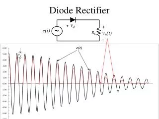
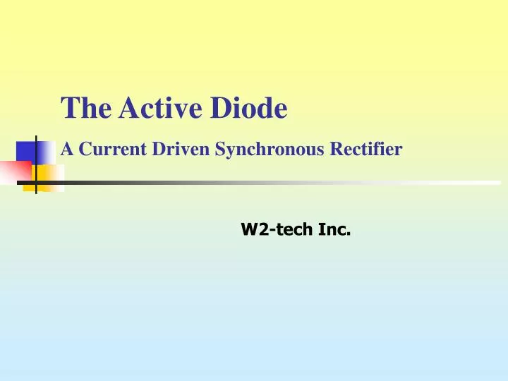
The Active Diode A Current Driven Synchronous Rectifier. W2-tech Inc. Demand for Low Voltage High Current Power Converters. Modern Microprocessor operates at low voltage and high current The future demand will go for less than 1 V and more than 150A.

E N D
The Active DiodeA Current Driven Synchronous Rectifier W2-tech Inc.
Demand for Low Voltage High Current Power Converters • Modern Microprocessor operates at low voltage and high current • The future demand will go for less than 1 V and more than 150A
Reasons for low voltage & high current • Switching time is shorter between close voltage levels • Less loss due to capacitance • IC sub micron technology requires low operating voltage • Large number of devices need high current
Synchronous Rectification is needed • In order to handle high current at low voltages, SR is needed • Low Rdson MOSFET greatly reduces losses at the output rectifier
There are many problems with conventional SR • Different topologies need different drive circuit design • Active clamp on the primary side is often needed
Problems with conventional SR …cont’d • MOSFET driving voltage is directly coupled to the input voltage • Gate voltage limits input voltage range • Gate drive voltage not optimized Input voltage 120V to 380V
Body diode conduction T1 T1 I/P voltage M1 M2 gate T1 O/P voltage M2 M1 gate 0.6V M1M2 conduction voltage 0.1V M1, M2 power loss M1 current M2 current Problems with conventional SR …cont’d • Leakage inductance produces long body diode conduction period • This increases dissipation and greatly reduces efficiency • Bad at high frequencies
Vo Vo- Vo+ Problems with conventional SR …cont’d • MOSFET is a bi-directional switch • Converters with SR cannot be connected in parallel, as reverse current will flow between converters
Problems with conventional SR …cont’d iL • MOSFET is a bi-directional switch • No discontinuous mode • Poor light load efficiency because of current peaks
Problems with conventional SR …cont’d • The gate drive will be lost after the transformer is reset in a forward converter • Active clamp on the primary side is often needed • More components and violation of patents SR1 SR1 SR2 SR2 Vgs(SR1) Vgs(SR2)
Desired Solution • The SR should turn on and off according to current flow • This makes the SR behaves like a diode • Solves all aforementioned problems
The Active Diode – Basic configuration Current sense circuit M1 N1 N2 Amplifier N3 N4 D2 D1 • N1 is the current sense winding • N2 amplify voltage at N1 • N1 N3 & D1 form energy recovery circuit • N4 & D2 form reset circuit Energy recovery circuit Reset circuit
Basic Operation of the Active Diode Voltage drop Vcs across current sense winding N1 is depend on the winding ratio of N1 to N3 and voltage source Vo Ii Voltage source Vo can be any voltage source in a converter, e.g. output voltage M1 Voltage across winding N2 or gate drive voltage Von of SR depends on ratio of N2 to N3 and voltage Vo N1 N2 T1 N3 N4 D2 D1 Vo
Toff Ton_d Ii Von VN2 Vo VN3 Vo VN4 Toff_d Waveforms Ii M1 N1 N2 T1 N3 N4 D2 D1 Vo
K A A K AD K A Active Diode – the way to a perfect diode It's a Diode a perfect Diode
AD AD It is better than Synchronous Rectifier Sync Rect Active Diode • Complicated primary circuit • Converter cannot be paralleled – Reverse current • Poor efficiency at low load • Special driving circuits SR are needed for different topologies • Sensitive to transformer leakage inductance • Limited input voltage range • Simple primary circuit • Discontinuous mode is allowed • Good low load efficiency • Converter can be paralleled • Works just like a diode
K K A A K A AD K A It is far better than Schottky diode • Inherent forward Volt. drop • Low reverse voltage • No or little avalanche rated • No inherent Volt. drop • high reverse voltage • 100% avalanche guaranteed
K A 0.24 V 7.8 m K A 9 m SCK Diode or Active Diode? Average 30V SO8 MOSFET State of the Art 30V SCK
SCK 2.8W losses @ 10A AD 0.7W losses @ 10A AD SCK Diode VS Active Diode
AD IR1176 AD Design engineer’s consideration
The Active Diode is • 5 times lower losses than state of the art Schottky diode • 50 times lower losses is also possible • 100% avalanche guaranteed • Only MOSFET solution can ensure important no load power <0.3W • Cheapest solution compared with other Sync-Rect solution • Replace diode on all old and new converter designs • Much higher operating temperature than Schottky diode • Wide frequency & voltage range from 50 Hz to 500kHz and 12V to 1000V
The Active Diode works in all topologies Flyback Forward
It works just like a low loss diode Half Bridge centre tap Current Doubler
……. in different topologies and many others…. Resonant converter
Conclusions • A new “Active Diode” technology is presented • A kind of current driven synchronous rectifier which solves many problems of the conventional Sync Rect • Well proven by many converter designs