Download
1 / 18
210 likes | 461 Views
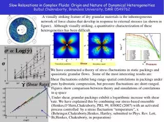
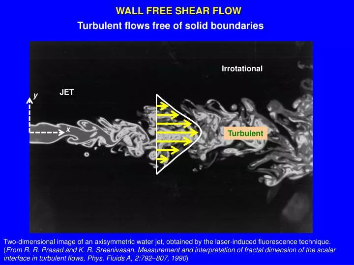
WALL FREE SHEAR FLOW. Turbulent flows free of solid boundaries. Irrotational. JET. y. x. Turbulent.

E N D
WALL FREE SHEAR FLOW Turbulent flows free of solid boundaries Irrotational JET y x Turbulent Two-dimensional image of an axisymmetric water jet, obtained by the laser-induced fluorescence technique. (From R. R. Prasad and K. R. Sreenivasan, Measurement and interpretation of fractal dimension of the scalar interface in turbulent flows, Phys. Fluids A, 2:792–807, 1990)
WAKE http://www.ifh.uni-karlsruhe.de/science/envflu/
x Laser-Induced Fluorescence (LIF) VISUALIZATION OF AN AXISYMMETRIC TURBULENT JET, C. Fukushima and J. Westerweel, Technical University of Delft, The Netherlands
Turbulent Kinetic Energy (q2) Balance in a Jet x Laser-Induced Fluorescence (LIF) VISUALIZATION OF AN AXISYMMETRIC TURBULENT JET, C. Fukushima and J. Westerweel, Technical University of Delft, The Netherlands
q2 <v2 > <u2 > y m2/s2 <w2 > x -<uv> y
Turbulent Kinetic Energy (q2) Balance in a Jet x No local accelerations No viscous transport Part of the shear production = 0 No buoyancy production Laser-Induced Fluorescence (LIF) VISUALIZATION OF AN AXISYMMETRIC TURBULENT JET, C. Fukushima and J. Westerweel, Technical University of Delft, The Netherlands
Gain y m2/s3 x y Loss
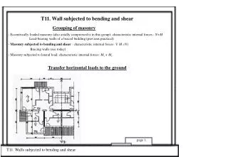
WALL-BOUNDED SHEAR FLOW 0.99U0 http://www.symscape.com/node/447 Nominal limit of boundary layer U0 Viscous sublayer For fully developed, bounded turbulent flow (not changing in x):
Function of z only Function of x only z CONSTANTS! centerline or surface
in boundary layer: stress is a function of x and z z z edge of boundary layer
Near the wall – Different Layers z ū (x) Only involve mass dimension u(x,z) Should appear together in nondimensional groups Friction Velocity http://furtech.typepad.com/
This relates 4 variables involving the dimensions of length and time According to the PI THEOREM, this relationship has 4 variables and 2 dimensions Then, only two (4 – 2) non-dimensional groups can result: Law of the Wall Inner part of the wall layer, right next to the wall, is called the viscous sublayer– dominated by viscous effects
z (m) = z+ν/u* viscous sublayer buffer layer logarithmic layer
outer layer Velocity defect law Equating and multiplying times z/u* logarithmic layer Karman constant = 0.41 buffer layer viscous sublayer Law of the wall
Karman constant = 0.41 Integrating: From experiments: Velocity distributions for the Overlap layer, Inertialsublayer, Logarithmic layer Logarithmic velocity distribution near a boundary can also be derived from dimensional analysis
can only depend on z, and the only relevant velocity scale is u*
Data from Ponce de Leon Inlet Florida FloridaIntracoastal Waterway