Download
1 / 12
120 likes | 222 Views
Phased Refurbishment of Relays and Communication Channels. Traditional panel with analogue relays and traditional control. Modern panel with numerical multi-function relay. Communication Channel Options. DCE. DCE. DCE. DCE. DCE. DCE. DCE. DCE. Dedicated channel FO shared

E N D
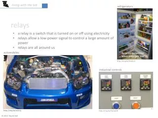
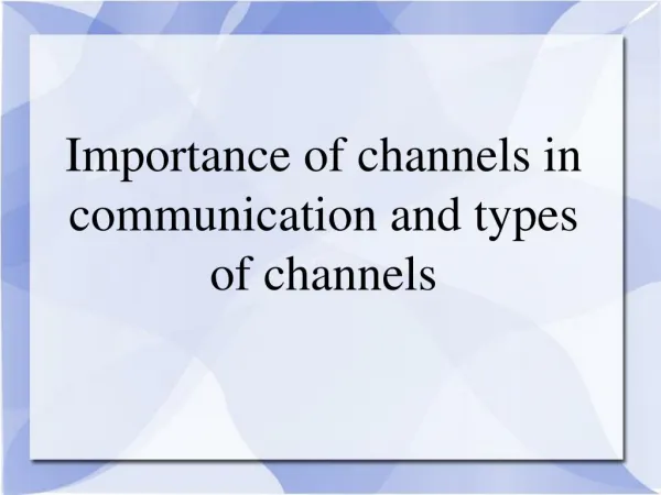
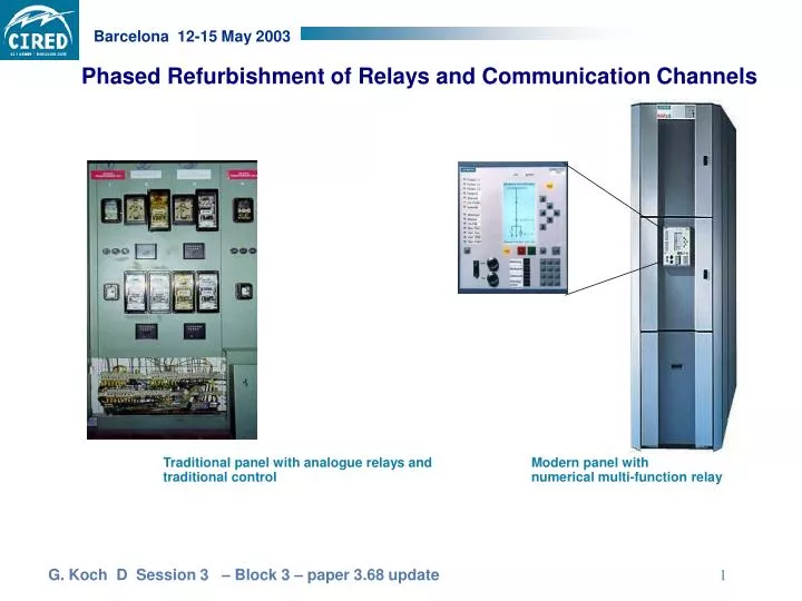
Phased Refurbishment of Relays and Communication Channels Traditional panel with analogue relays and traditional control Modern panel with numerical multi-function relay
Communication Channel Options DCE DCE DCE DCE DCE DCE DCE DCE Dedicated channel FO shared shared channel non-switched channel switched, time shared packet switching suitable? R R DCE WDM WDM DCE M M DCE DCE R R R M R M Transportation network R M R M R M R M
A/D D/A 2 Options Analogue relay Analogue relay Digital channel 87L 87L Digital relay Digital relay Digital channel 87L 87L
One feeder, one IED! Protection DCE % 0 50 100 Metering Feeder data base DCE I Control O V SCM Remote Interrogation and Data Acquisition for DMS R2R R2S Legend: DCE digital communication equipment SCM supervisory control mimic R2R relay-to-relay coms R2S relay-to-subscriber coms
Continuous event-driven inquiry load data fault reports set points status indication dynamic data static data WEB Publishing Enterprise subscribers Web clients Relay engineer maintenance staff etc. mobile Intra net Substation Router Ethernet TCP/ IP Bay Data publishing Content provider Relay or bay controller with embedded WEB server
Option 49 51 87L 85 50 79 SI FC FR M 86 RA Channel to remote end • Legend : • 87L Differential relay • 50/51 Back-up overcurrent • 49 Thermal overload • Intertrip channels • 86 Lock-out • FR Fault Recording Memory • M Metering • FC/SI Supervisory feeder control • RA Remote access (e.g. intranet) Scope of Functions
Some 100m BH FO 87/49 87 Teleprotection and intertrip channel
Optional Communications Media E O O E E O O E O E O E Optional communication media Optical fibres 87L 87L Pilot wires Digital Coms network ISDN
‘Quality of Supply, QoS’ Digital SDH- Communication- network e o o e Mux Mux e o • Latency, slot time (not necessarily data rate) • latency band ( min. to max.), differential latency, critical net load, • Propagation time • Propagation time differential • dependability, Bit Error Rate BER • BER for : <1 min, <1 sec, non-available if BER >10-3 for >10sec • BER under fault conditions? • measurement within time windows <100ms • loss-of-channel, hot stand-by, back-up routes • Route switching may cause nuisance alarm of relay monitor • hostile environment, EMC, IEC 255 • security • inherent measures, e. g. permissive signals • protocol security
V 2 V 2 Induced Voltage along a Pilot Wire Pair I = fault current barrier transformer V V2 V V1 Legend I earth fault current 0 flux generated by E/F - current V induced voltage E = 2f • M •I •L • r1 • r2
Induced Voltage, Calculation Example Legend f frequency f = 50 Hz M induction between power and pilot cable per km, for a distance of 80 cm between cable and pilot wires, and for an earth conductivity of 0.02 s/m e.g. M = 1.347 mH/km I earth-fault current e.g. I = 15 kA L length of parallel running cables e.g. l = 8.4 km r1 reduction factor of h.v. cable r1 = 0.2 - 0.4 for single conductor oil cables e.g. r1 = 0.3 r1 0.1 for cables in steel pipes r2 reduction factor of pilot cable r2 = 1 for unscreened cables r2 0.4 for best screening e.g. r2 = 0.4
Galvanic Separation of Pilot Wire and Relay Potential relay panel pilot cable sealing end barrier transformer prevents 'dirty potential' to enter the relay panel 20 kV 500 V 'clean potential' 'dirty potential'