Download
1 / 10
100 likes | 220 Views
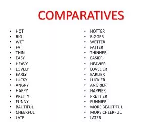
Optical Position Sensor for the VWS. Approaches, Effe cts and Comparatives. Jose Luis Sirvent Supervisor: Jonathan Emery. Student Meeting 10 October 2011. 1.Possible approaches to take into account. 1 2 3

E N D
Optical Position Sensor for the VWS. Approaches, Effects and Comparatives Jose Luis Sirvent Supervisor: Jonathan Emery Student Meeting 10 October 2011
1.Possible approaches to take into account 1 2 3 4 5 6
2. Effects to consider • Diffraction Effect: • After crosing each of the holes the beam experiments difraction. • Fresnel or Fraunhofer dispersion : • “Mutual interference of secondary wavelets starting from portions of the wave front which are not blocked by the obstacle or from portions of the wave front which are allowed to pass through the aperture.” • Rayleigh/Frenel distance: • Zf(50um) =2.94mm / Zf(75um) = 6.61mm / Zf(100um) = 11.76mm / Zf(150um) = 26.47 mm • In the worst case there is no significative dispersion effect if Z < 3mm • Fresnel Dispersion in the when the separation between disk is in the range 0-3 mm / Fraunhover in the range > 3 mm. (Bigger apertures --> Bigger distances)
2. Effects to consider • Collimated light VS Non Collimated
2. Effects to consider • 850 nm VS 1550nm
3. Option 5 • Advantages: • In ideal conditions we are able to obtain the best resolution (movements of 50um) • Only 1 device to align • It’s easier to couple light into the fiber. • Disadvantages: • The optics aren’t tested under radiation • Synthetic fused silicia • The chamber should be wither • Two more components, stationary disk + collimator • We are crossing about 400 holes • Light (diffraction Fresnel or Fraunhofer) • Interference pattern (Huygens principle)
4. Option 6 • Advantages: • In ideal conditions we are able to obtain the best resolution (movements of 50um) • Only 1 device to align, but with a lot of precision. • High Light coupling, ideally 100%. • Disadvantages: • The optics aren’t tested under radiation • Synthetic fused silicia • The chamber should be wither • Two more components, stationary disk + collimator • We are using the reflection of 1 slid • High accuracy in focal distance (In first calculus the tolerance is +- 0.18mm) • High accuracy in the angle of incidence.
6. Component search • A) Circulators
6. Component Search • B) Collimators and Focusers