Download
1 / 46
460 likes | 581 Views
Auto-alignment of the SPARC mirror. 28-11-2013 W.S. Krul. Movie. Presentation goal. To inform you about : The problem Development of a solution using modeling and experiments Conclusions & recommendations. Introduction. Manual alignment : Experienced operator

E N D
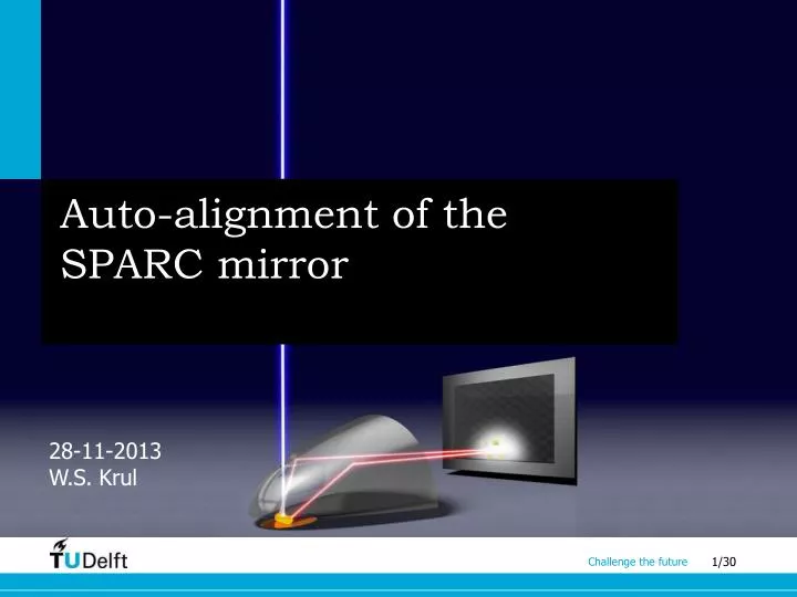
Auto-alignment of the SPARC mirror 28-11-2013 W.S. Krul
Presentation goal Toinformyouabout: • The problem • Development of a solution usingmodelingandexperiments • Conclusions & recommendations
Introduction • Manual alignment: • Experienced operator • Takes up to 1 hour • SPARC: • Angle-resolvedmeasurements • Spectrometry
Problemformulation • Develop auto-alignment solution • Using first principles modeling • In 3 DoFs • Meeting alignment requirements
Alignment concept • Advantages: • Current manual alignment setup • No extra hardware needed • Low cost • Disadvantages: • Unknownwhether concept candifferentiatebetweenDoFs
Modeling • Torelate the images to the misalignments, a model is needed • 2 modeling approaches: • Build backward model • Findan image metricthat is maximizedwhen the system is aligned Misalignment Image Forward image model
Modelingassumptions • Geometricoptics • Point source as excitation point • Misalignmentsmodeled as source location • Perfect lens & perfectlyshapedmirror • Onlyx,y,z, misalignments
Model basics • 2D-3D • 2D analogy: • Calculate “amount of angle” • Apply radiant intensity • 3D: • Analytical approach • Backward ray model
Inverting the ray model • Inversion: 1-1 mapping
3D model • 3D: • Forward ray model (closed-form) • Backward ray model (numerical) • Forward image model • Toguaranteefunctionality: • Source nearfocal point • Imagedplanenearfocalplane • Numericalinversionpossible (fitting techniques)
Model validation • For validation 2 conditions must be met: • Experimentalconditionsshould match model parameters andassumptions • The model must captureall important physicalprocesses • 2 steps: • Quantitativevalidationwith model • Qualitativevalidationwithexperiments
Model-model validation • Misaligned case 0,1518 1,658 x 10-3 0,0371 1,435 x 10-3 Max error: MAE: Max error: MAE:
Experimentalvalidation • Aligned case: 0,228 8,610 x 10-3 Max error: MAE:
Experimentalvalidation • Possiblecauses mismatches: • Exp. conditionsdon’t match model parameters • Unmodeledeffects • Model & experimentsinsensitivetomisalignments • Find image metric
Alignmentusing image metric • Total intensity(TI) metric • Diaphragm
Conclusions • Backward model notfeasible • Quantitativevalidationwith model • Partialexperimentalvalidation • Differences images, similarbehaviour • Maximizing TI metricpromising solution • Accuracyachieved of 10,93 µm • Diaphragmalignmentnotcritical • Source type dependent
Recommendations • Includeyawand pitch • Search algorithm • Aperturesizes • Validation: opticalbench
3D • Forward ray model: • Forward image model: (landing point) (emissionangles)
Appendix • Resultscombinedmisalignments