Download
1 / 1
10 likes | 196 Views
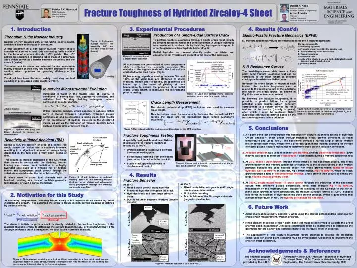
Patrick A.C. Raynaud PhD. Candidate Materials Science and Engineering. Donald A. Koss Professor Emeritus Materials Science & Engineering Arthur T. Motta Professor Nuclear Engineering Materials Science & Engineering. Radial direction. Circumferential direction.

E N D
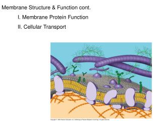
Patrick A.C. Raynaud PhD. Candidate Materials Science and Engineering Donald A. Koss Professor Emeritus Materials Science & Engineering Arthur T. Motta Professor Nuclear Engineering Materials Science & Engineering Radial direction Circumferential direction Figure 1: Light-water nuclear reactor fuel assembly (left) and fuel rod cross section (below) U02 cladding 250m 500m Figure 2: Hydride rim (top) and blister (bottom) in nuclear fuel cladding tube. Crack initiation in blister Crack initiation in hydride rim Crack propagation along hydrides Figure 8: Picture and schematic representation of the 4-point bend specimen and fixture. Through thickness crack growth Figure 3: Crack initiation in reduced ductility zones of the cladding surface (hydride rim or blister) and subsequent crack propagation through the cladding surface during a RIA Blister Cracked hydrides B17 190m Crack Profile Crack Profile Primary voids (cracked hydrides) Uncracked hydrides Crack Surface Crack Surface Ductile dimples Ductile dimples Fracture Toughness of Hydrided Zircaloy-4 Sheet 1. Introduction 3. Experimental Procedures 4. Results (Cont’d) Production of a Single-Edge Surface Crack To perform fracture toughness testing, a single crack must initially be present across the width of a bend specimen. A unique technique was developed to achieve this by localizing hydrogen absorption in order to generate a linear hydride blister (Fig.5). Radial hydrides are present directly under the blister and circumferential hydrides are present in the rest of the substrate Elastic-Plastic Fracture Mechanics (EPFM) Zirconium & the Nuclear Industry Nuclear energy provides 20% of the USA’s electric power, and this is likely to increase in the future. A fuel assembly in a light-water nuclear reactor (Fig.1) consists of a series of fuel rods containing fissile material in the form of uranium dioxide (UO2) pellets. The UO2 pellets are contained in cladding tubes made of a zirconium alloy which serves as a barrier between the pellets and the coolant (water). Zirconium and its alloys are selected for this application mainly because of their very low neutron absorption cross-section, which optimizes the operating efficiency of the reactor. Zircaloy-4 has been the most widely used alloy for fuel cladding in pressurized water reactors (PWR). KQ fracture toughness values are calculated using the J-integral approach: Bn: specimen width b: remaining ligament Apl: plastic energy spent by the applied load K: stress intensity factor at crack tip E: Young’s modulus ν: Poisson’s ratio η: ratio of the plastic J-integral to the total plastic work done per unit uncracked area : geometry factor Figure 5: cross-section of a cracked test specimen All specimens are pre-cracked at room temperature while monitoring the acoustic emission. The majority of the signals scale with the load and are attributed to the load frame. (Fig.6) Higher energy signals occurring between 50% and 100% of the yield load are attributed to blister cracking. Hence prior to testing, all specimens are loaded up to the onset of yielding at room temperature to ensure the presence of an initial crack. Crack length is measured via micrographs prior to testing. K-R Resistance Curves The load-displacement data from a four-point bend fracture toughness test can be correlated to the crack length to produce crack growth resistance (K-R) curves. Because the crack length is known at each instant, the fracture toughness can be related to the microstructure of the substrate into which the crack grows, as shown in Fig.10 for a room temperature test. By knowing the fracture toughness, it is possible to predict failure for a given potential crack length, which generally corresponds to a certain service life for a fuel rod in the reactor (usually in years), after which it must be replaced. Safety guidelines can thus be defined based on the fracture toughness failure criterion. In-service Microstructural Evolution Immersed in water in the reactor core at ~300°C, in conditions of strong heat flux, aggressive chemistry and radiation field, Zr alloy cladding undergoes uniform corrosion in its outer diameter: Unlike radiation damage, which appears to saturate rather early in reactor exposure (~months), hydrogen pickup continues as long as corrosion is taking place. This results in the precipitation of hydride platelets in the Zircaloy-4 matrix, as well as the formation of reduced ductility zones such as hydride rims or blisters (Fig.2). Figure 6: Load and corresponding acoustic emission versus time for a test to failure Crack Length Measurement The electric potential drop (EPD) technique was used to measure crack length. This technique uses the relationship between the normalized EPD across the crack and the normalized crack length (Johnson’s equation): Figure 10: K-R resistance curve for a room temperature fracture toughness test, i.e. fracture toughness KQ as a function of crack length increment δa. 5. Conclusions Figure 7: Current and potential lead placement locations for the EPD technique • A 4-point bend test configuration was designed for fracture toughness testing of hydrided CWSR Zircaloy-4 sheet under through-thickness crack growth conditions at room temperature and up to 400°C. The specimens contain a narrow strip of brittle hydride blister across their width, which form a pre-crack upon initial loading, allowing for the use of elastic-plastic fracture mechanics to determine crack growth initiation conditions. • Acoustic emission was used to monitor pre-cracking, and the electric potential drop (EPD) method was used to measure crack length at each instant during a fracture toughness test. • At 25°C, mode I crack growththrough the thickness of the specimen occurs. The crack growth behavior and fracture toughness are sensitive to the microstructure of the hydride particles beneath the solid hydride blister. For crack growth within radial or mixed hydrides,Kq 25 MPa√m. In contrast, Kq is much higher, Kq 75 MPa√m, when the crack grows through a zone of circumferential hydrides. Crack growth then occurs by linking the large hydride-initiated primary voids. • At 300°C, stable mixed mode I+II crack growth through the thickness of the specimen occurs with extensive plastic deformation. Initial data indicate Kq 83 MPa√m, independent on the microstructure. Despite the similarity of this Kq-value to that for in-plane crack growth at room temperature, the fracture surfaces formed at 300ºC suggest little direct involvement of hydrides in the crack growth process, which is quite unlike that at room temperature. In fact, the hydride precipitates do not crack. • Fracture Toughness Testing • A specially designed 4-point bend fixture (Fig.8) allows for fracture toughness testing up to 400°C. • Uniform bending is achieved between the center loading-pins • Stress fields resulting from the loading pins do not interact with the crack tip • Stable crack growth achieved in displacement control Reactivity Initiated Accident (RIA) During a RIA, the ejection or drop of a control rod would cause the fission rate to suddenly increase, resulting in a significant amount of energy being deposited in the fuel over a very short period of time. This results in thermal expansion of the fuel, which then comes in contact with the cladding. Further loading can cause crack initiation in a highly hydrided spot such as a hydride rim or hydride blister, and subsequent crack growth through the substrate material under the rim or blister (Fig.3). If failure were to occur, fuel channels may be blocked, resulting in a loss of coolable geometry, fuel damage, or even a partial meltdown. 4. Results Fracture Behavior • At 300°C: • Mixed mode I+II crack growth at 45° angle due to shear deformation • No hydride cracking • Ductile failure of the Zircaloy-4 substrate (large ductile dimples) • At 25°C: • Mode I crack growth along hydrides • Fractured hydrides alongside the crack • Hydrides crack and form large primary voids • Ductile failure in between hydrides (ductile dimples) 2. Motivation for this Study At operating temperatures, cladding failure during a RIA appears to be limited by crack initiation and growth. It is assumed the strain to failure in high-burnup cladding is defined by the relationship: total = crack initiation + crack propagation Previous studiesThis study The strain to initiate or grow a crack is directly related to the fracture toughness of the material, thus it is critical to determine the fracture toughness (KQ) of hydrided Zircaloy-4 for through thickness crack propagation. No such data is currently available. 6. Future Work • Additional testing at 300°C and 375°C while using the electric potential drop technique for crack length measurement. Work in progress. • Finite element modeling of the 4-point bend test must be performed to validate the EPFM analysis used. In particular, J-integral calculations must be implemented to determine the geometric factors η and and compare them to the literature. Work in progress. • The applicability of this fracture toughness failure criterion to existing life prediction codes used for power plant licensing must be investigated. Guidelines to implement the criterion must be defined. Acknowledgements & References Reference: P. Raynaud, “Fracture Toughness of Hydrided Zircaloy-4 Sheet,” M.Sc. Thesis in Materials Science and Engineering, The Pennsylvania State University, 2005 The financial support for this research is provided by the N.R.C. Figure 4: Finite element modeling of a hydride blister submitted to a four point bend fracture toughness test (Von Mises stress, yielding is represented in red). The failure of the cladding due to crack growth is controlled by its fracture toughness. Figure 9: Fracture behavior at 25°C and 300°C.