Download
1 / 28
280 likes | 398 Views
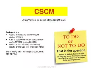
CSCM-7TeV. Status of CSCM-7TeV project. M. Bajko, M. Bernardini, B. Bordini, k. Brodzinski, J. Casas-Cubillos, Z. Charifoulline, G. D’Angelo, R. Mompo, A, Perin, M. Pojer, F. Savary, M. Solfaroli Camillocci, J. Steckert, H. Thiesen J.P. Tock A. Verweij, G. Willering, D. Wollmann,. H. Thiesen

E N D
CSCM-7TeV Status of CSCM-7TeV project M. Bajko, M. Bernardini, B. Bordini, k. Brodzinski, J. Casas-Cubillos, Z. Charifoulline, G. D’Angelo, R. Mompo, A, Perin, M. Pojer, F. Savary, M. Solfaroli Camillocci, J. Steckert, H. Thiesen J.P. Tock A. Verweij, G. Willering, D. Wollmann, H. Thiesen 30 August 2012
The CSCM Project • The CSCM (Copper Stabilizer Continuity Measurement) is a qualification tool (not a measurement tool) that can determine the maximum safe energy per sector by testing the main circuits, RB and RQ. • Before LS1: CSCM is a tool that can give statistical proof of the quality of the contacts in the diode leads • After LS1: CSCM is a tool to qualify the entire 13 kA circuit (joint + pigtail + HTS lead + diode + diode leads) • It reproduces the very process we are trying to avoid during operation, the thermal runaway of a joint. • It manages to do this by using similar conditions to those during a quench, but has no energy stored in the magnets so that the thermal runaway can safely be stopped by an interlock process. • This is achieved by doing the test at a temperature of about 20K, so that the magnets are no longer superconducting and the current passes through the bypass diode connected to all main magnets. H. Thiesen – 30 August 2012 – TE-MPE
What will the CSCM qualify? • All main circuits (RB, RQD, RQF) • All interconnection splices • All current lead-busbar connections at the DFB • All bypass diode paths Defect: Potential Consolidation: No Defect: ? Consolidation: No H. Thiesen – 30 August 2012 – TE-MPE Defect: Yes Consolidation: Yes (DFBs included)
Initial objective • The initial objective of the CSCM project was to determine the maximum safe energy of the LHC before the splice consolidation • Due to several nonconformities, this energy was limited at 5 TeV • MB circuits: 9 kA – 68 s • MQ circuits: 9 kA – 15 s H. Thiesen – 30 August 2012 – TE-MPE
New objective • The new objective of the CSCM-7TeV project is to qualify the 13 kA circuits of the LHC after the splice consolidation • The maximum energy is now 7 TeV • The qualification should correspond in terms of heat deposition to an exponential decay from 12 kA with tau = 100 s (MB) or 30 s (MQ) • The qualification should go to similar currents as the LHC because some contact resistances are strongly current dependant H. Thiesen – 30 August 2012 – TE-MPE
4 proposals of cycle (MB circuits) Too high voltage(900 V) H. Thiesen – 30 August 2012 – TE-MPE
4 proposals of cycle (MQ circuits) Too high voltage(900 V) H. Thiesen – 30 August 2012 – TE-MPE
I_nom with linear decay • Advantages • Reach nominal current (validation of the diode splices) • Current cycle is similar to an exponential decay • Voltage across the circuits is limited at 400 V • Disadvantages • Protection of the splices by over voltage can not be optimize (see next slides) • Over current in the power converter (see next slides) H. Thiesen – 30 August 2012 – TE-MPE
Option B: linear decay with limited current • Advantages • Over current in the power converter is limited • Disadvantages • Diode leads can not be tested at nominal current H. Thiesen – 30 August 2012 – TE-MPE
Circuit protection system Board A Board B nQPS BS Board A: EE012<->EE013 (Bus bar) nQPS BS Board B: EE014<->EE015 (Bus bar + 2 DLs) What about to swap the voltage taps? (AW) “nQPS BS” boards will be replaced by “nQPSmBS” boards. No any additional patches, voltage taps will be the same. H. Thiesen – 30 August 2012 – TE-MPE We propose to have some segments with special patches during the type test so as to swap the voltage taps
Circuit protection system Input range of the mBSboardsis ±2.5V H. Thiesen – 30 August 2012 – TE-MPE Input stage of the mBS boards have to be be modified for the MQ circuits and for several segments of MB circuit Assuming a segment length of 38 m (RB) and 114 m (RQ) dVsegm/dt is taken during ramp down only
Circuit protection system • mBS hardware modification add 15k add 15k increases input range from +/-2.56V to +/-10V H. Thiesen – 30 August 2012 – TE-MPE
Circuit protection system • During the ramp up (and possibly short plateau) protection is not needed, considering the small amount of dissipated energy in the circuit, and previous tests done. • Due to the non constant current in the circuit under tests, protection will be entirely based on setting a threshold for dV/dt, which will only be acting during the ramp down. • Protection of the HTS leads has to be checked, but will remain based on a threshold for V. The actual 3 mV, 100 ms will not be possible. A choice has to be made to increase either Vthr or the decision time. With the entire bus going above 80 K, we might always quench the HTS. To be discussed and tested in SM18 !!! H. Thiesen – 30 August 2012 – TE-MPE
Circuit protection system • Conclusion • Current lead protection system will be the same as already installed (maybe different thresholds) • mDQQBS boards had been produced in 2011 (900 pieces) • Hardware modification required to increase input range • Modification is only acceptable as “professional rework” since cards are used for protection. managed by EM section • Firmware has to be modified to adapt to new requirements • Pure dV/dt algorithm is very sensitive to noise ! • Intensive testing has to be done to ensure reliable operation • Specialized supervision software has to be developed, and tested (Threshold calculation, database for thresholds and settings, data acquisition… LOTS of work !)
Circuit protection system • Next Steps • Evaluation of mDQQBSxt (mBS extended input range) • Writing a prototype firmware based on pure dvdt algorithm • Intensive testing ! • Priority of this project has to be defined ! • Software side of this project up to MPE-MS section • ECR is mandatory (who’s writing it ?) • Scheduling/resources (who’s actually performing the test ?)
Powering aspects • The CSCM-7TeV project requests a [400V/12kA] • The ratings of RB power converter is [200V/12kA] • 2 bridges in //: [200V/12kA] • 2 bridges in series: [400V/6.5kA] • Only the second option is possible L L L L Normal configuration Output voltage limited at 200 V Series configuration Output current limited at 7 kA H. Thiesen – 30 August 2012 – TE-MPE
Powering aspects • The 2 bridges of the same RB power converters connected in // L • Advantages • Light modification • This configuration has been tested in P-Hall last year at 6.5 kA • Disadvantages • Over current in the bridges: 12 kA instead of 7 kA • Blocking point => we do not have the characteristics of the water cooled heatsinks Over current area L Max. bridge voltage H. Thiesen – 30 August 2012 – TE-MPE
Powering aspects • RB powering configuration 500 V 500 V 400V 200V RB 300 V 400V • Energy extraction system is not needed to protect the circuit during the tests (low energy stored ins the circuit) to be confirmed by Arjan • Max. voltage across the circuit during the tests is less than 600 V. 1x240mm2 1x240mm2 Rearth (500V) 200V 0V H. Thiesen – 30 August 2012 – TE-MPE
Powering aspects • From Standard ELQA procedure (Edms:788197) • From SM18 Test benches: • Proposed ELQA Test for CSCM • Pressure in the cold masses of the ARC: P > 5.5 bar (> 4.0 bar is acceptable) • Pressure in the DFBAs: P > 1.8 bar (same condition as TP4-C) Tests in the similar conditions at 80 K H. Thiesen – 30 August 2012 – TE-MPE
Powering aspects • RQ powering configuration 100 V RQF RB RB Earth system 1x240mm2 • Energy extraction system could be needed to protect the circuit during the tests (low energy stored ins the circuit) to be confirmed by Arjan • Max. voltage across the circuit during the tests is less than 600 V. H. Thiesen – 30 August 2012 – TE-MPE
Powering aspects • From Standard ELQA procedure (Edms:788197) • From SM18 Test benches: • Proposed ELQA Test for CSCM • Pressure in the cold masses of the ARC: P > 5.5 bar (> 4.0 bar is acceptable) • Pressure in the DFBAs: P > 1.8 bar (same condition as TP4-C) The circuit has never been tested at 600V H. Thiesen – 30 August 2012 – TE-MPE ELQA under this condition has not been done before, but it should not be a problem!
Powering aspects • Conclusion • CSCM-7TeV requests 12kA and 400V (instead 6kA and 400V for 5 TeV) • Only the solution with both SCR bridges connected in series is feasible • To reach 12kA, the SCR bridges has to be able to support over current (up to 170% of I_nom) during about 70 s • One of the main challenge for the converter is also the current control when the impedance of the circuit changes • Next steps • Identify the characteristics of the diodes at 20 K (planned in September) • Define the limitations of the SCR bridge (expected before end this year) H. Thiesen – 30 August 2012 – TE-MPE
Cryogenic aspects • Same initial conditions as the last year • Arc magnets stabilized at • T = 15 - 25 K (±1 K) • P = 5 bar (±0.5 bar) • DFBAs • Bottom of the copper part of the current leads stabilized at T = 35 – 45 K • P = 1.8 bar (no liquid helium in the DFB) • But with more energy dissipated during the tests • Arjan could you estimate the max. energy for MB and MQ circuit • Remark: • The requested configuration never done before but good feeling to respect requirements defined above. H. Thiesen – 30 August 2012 – TE-MPE
Cryogenic aspects • Main issue is still the 13 kA current leads CV891 WRL (~1.08 bar) TT893 Line C (~5 bar) CV930 - LHe filling TT891A 40/35 K Line D ~12 K GHe (1.25 bar) Radiation from ~70 K screen thermal • The bottom of the copper part of the current leads can be cooled to 35 K (it should be possible when line D at 20 K as well), limits: frozen head of the current lead -> interlock on CV891 • The initial temperature of the busbar should be guaranteed by conduction at ~22 K when regulation at 40 K , ~20 K when regulation at 35 K (tested with LHe in the neibhour magnet) • No liquid helium at 4.5 K to stabilize the bottom of the current leads 4.5 K H. Thiesen – 30 August 2012 – TE-MPE
Cryogenic aspects • Choice of the sector for the type test • Potential problems for the CSCM campaign • When cold feet circuit active during the test there is a risk to have TT_beam screen < TT_cold bore. H. Thiesen – 30 August 2012 – TE-MPE
Cryogenic aspects conclusion • Conclusion • No show stopper has been identified • The 600V across the circuit is not an issues for the cryogenic instrumentation • Type test must be done in sectors 12, 23, 56 or 67 • Potential issue: TT_beam screen < TT_cold bore • Next steps • Test of the 13 kA current leads in SM18 with the CSCM conditions is mandatory • Test can be possible in December H. Thiesen – 30 August 2012 – TE-MPE
Impacts on LS1 • If the CSCM tests have to be done after the LS1, type test must be done end the end of physic. • Estimated duration for the type test (1 sector with only 1 MQ circuit) is month (4 weeks) • 2 weeks for preparation • 2 weeks for the tests (5-6 hours between 2 cycles for cryogenic recovery and data extraction and analysis) • Type tests is planned in sector 23 (and or 34) • Estimated duration for the CSCM campaign after LS1 • 2 weeks for preparation in the shadow of LS1 • 2 weeks for the tests with maximum 2 sectors in // • 2 weeks for the recovery before the IST and powering tests • Total impact is estimated at 1 month (see Katy presentation in Chamonix) H. Thiesen – 30 August 2012 – TE-MPE
Conclusion • CSCM could be a powerful tool to qualify the main circuits at 7 TeV specially if the diode splices and the current lead splices are not consolidated • No showstopper have been identified • Several challenges have to be solved • Validation of the current leads • Validation of the power converter at 12 kA • Impact on LS1 is limited a 1 month, but CSCM project requires a lot of resources (mainly for MPE), especially people who are already busy during LS1. • If CSCM tests have to be done after LS1, type test is mandatory at the end of the 2012 physic run. Decision for the type test have to be taken in September • Type tests could be used to obtain more information concerning the diode lead quality (additional sequences). H. Thiesen – 30 August 2012 – TE-MPE