Download
1 / 21
210 likes | 353 Views
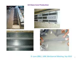
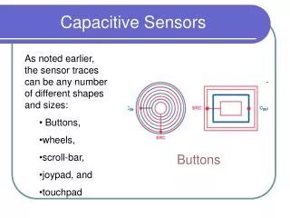
Measurements of US stave using ESPI and capacitive sensors 30 th August 2012. Three main tests carried out: 1. Vibrational modes (ESPI) 2. Cool down measurements Z direction (Capacitive sensors) 3. Cool down measurements X direction (Capacitive sensors).

E N D
Measurements of US stave using ESPI and capacitive sensors30th August 2012
Three main tests carried out: 1. Vibrational modes (ESPI) 2. Cool down measurements Z direction (Capacitive sensors) 3. Cool down measurements X direction (Capacitive sensors)
Markers showing positions of mounting brackets End mount brackets Capacitive sensors Cooling pipes Invar panel US stave mounted in environmental chamber.
Isotropic View of the US stave on the Invar Panel US stave 2 Dimensional Fixed Mounting Fixture US Brackets Fully Fixed Mounting fixture
End View 2 Dimensional Fixed Mounting Fully Fixed Mounting
The idea of constraining the 2nd fixed point which constrain in x and z directions only L-Spacer V groove spacer Fixed in 2 planes
Fixed point at x, y and z planes Fixed point at 2 planes
Constraint +ve X plane only Constraint –ve X and Z planes
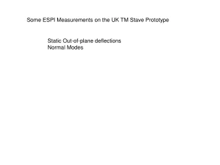
Measurements of vibrational modes using ESPI (Room temperature) Position of central bracket Vibrational modes (60 Hz)
Position of central bracket Vibrational modes (119Hz)
Position of central bracket Vibrational modes (185 Hz)
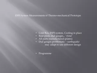
Cool down test measurements in Z direction using capacitive sensors Schematic of US stave showing locations of capacitive sensors
Conclusion: In the Z direction during cool down the whole stave is moving away from the sensors and it is also tilting more along the top edge. It is tending to tilt more along the right hand side than the left hand side.
In order to counteract the movement of the right hand side of the stave in Z direction, blocks were used to minimise the amount of movement allowed, free movement in X direction maintained.
Cool down test measurements in X direction using capacitive sensors Sensor Y Sensor Z Sensor X Schematic diagram of US stave showing capacitive sensor positions for x plane movement. Bracket Cooling pipe Capacitive sensor
Provisional Conclusions Normal modes don’t exhibit nodes at bracket locations. Stave movement highly dependent on end supports.