Download

1 / 17
170 likes | 397 Views
MICE Target. P J Smith & Target Team University of Sheffield CM 27 - RAL. Introduction. Target 1 - ISIS Target 2.3 – R78 – Vespel Bearings - Covered in Last CM Target 2.3 – Magnetic Measurements and results Target 2.3 – Magnetic Modelling and results Plans for Targets 1 & 2.4

E N D
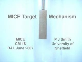
MICE Target P J Smith & Target Team University of Sheffield CM 27 - RAL
Introduction • Target 1 - ISIS • Target 2.3 – R78 – Vespel Bearings - Covered in Last CM • Target 2.3 – Magnetic Measurements and results • Target 2.3 – Magnetic Modelling and results • Plans for Targets 1 & 2.4 • Target 1 & 2.4 - Controller P J Smith - University of Sheffield
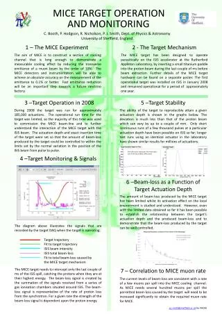
Target 1 - ISIS • Target continues to perform reliably (> 300 k + 50 k actuations) • No significant changes in the BCD distributions • No sign of dust production on view port – Latest photo 07/06/2010 • Target keeps running! P J Smith - University of Sheffield
Target 1 - ISIS • Target Pulses this year • Feb 28419 • Mar 18728 • Apr 22142 • May 51135 • Jun 73034 • Jul 39758 (to date) • Total 2010 233216 (+ 120000) 350000+ P J Smith - University of Sheffield
Target 2.3 – R78 Last CM Report • Target 2.3 was run in R78 on Vespel bearings for 2.1 million actuations – stopped for examination. • The bearings ran successfully but more wear was observed than we would have liked (none) - but there was not enough wear to stop operation! After 2.1m actuations there was a film of dust coating the internal components of the stator & some amalgamation of dust near the bearings. • There will be some mechanical changes made to target 2.4 to mitigate the production of the dust and to significantly reduce the possibility of it being transported into ISIS....but what is causing different amounts of wear between stators? • Stator 2.3 has been magnetically mapped in R79 to see if there are any magnetic anomalies. P J Smith - University of Sheffield
Target 2.3 – Magnetic Mapping • The stator is composed of 24 coils which are wired in a 3 phase configuration • These coils are switched through 6 states to provide the necessary acceleration or levitation of the target shaft. • The switching is dependent upon the position of the target shaft and control signals from the microprocessor. • A minimum of 2 states are required to permit assessment of all the coils. P J Smith - University of Sheffield
Magnetic Mapping • Diamond (c/o Emily Longhi) very kindly offered their assistance as they have a sophisticated rig for field mapping their wigglers/undulators • 3 axis hall probe that can be positioned to within a few microns Stator 2 was wired up to a DC power supply and the maximum possible continuous DC current supplied to a phase whilst the stator was field mapped. This was done for three of the six possible states (covers all 3 phases) Continuous current of 9 Amps P J Smith - University of Sheffield
Magnetic Mapping • Longitudinal Field - Solenoidal. This interacts with the magnets to provide the thrust force. The measured longitudinal field has been used to verify the magnetic model. • Radial Field. Visualise as a Quadratic? For a perfect coil this should vanishes at R = 0 – This field component has been used as a diagnostic to look for any imperfections in the magnetic structure. • The measurements by the Diamond Group indicates that the magnetic centre in stator 2 [defined where Br=0 (or dBr/dr = 0)] is offset by 300um Br D = 18.0 mm r P J Smith - University of Sheffield
Magnetic Mapping Why is there an offset of the magnetic axis? • Is this a feature of the coils or is it due to a mechanical displacement between the coil stack and the stator bore? • Or is it some other feature – weakly magnetic material outside the coils? The mapping is to be rechecked to ensure we obtain the same offset. Individual coils will be mapped to see what their field looks like. • Will we eventually be able to map Stator 1 (ISIS) to find out if the field symmetry is better for this stator? • All future stators to be mapped so that we can get a clearer picture of whether there is a correlation. P J Smith - University of Sheffield
Magnetic Modelling A model has been built in OPERA to try and understand the implications of running the permanent magnets off-centre • The model assumes perfect coils (imperfect coils would have been difficult to model given the time constraints) and allows the whole shaft with permanent magnets to be offset within the stator bore. The permanent magnets will then see a non-symmetric field. • It is implicitly assumed in the modelling that small mechanical offsets (model) will give similar results to small displacements in the Br=0 radial field axis due to magnetic imperfections. This effectively assumes that the field gradient is symmetric around the Br =0 axis. • The idea behind the model was to get a handle on what lateral forces/torque would be seen for small deviations. • Note that what is presented here is a summary – further details can be found in MICE note 309 P J Smith - University of Sheffield
Magnetic Modelling Very good agreement between the data and the model (Blue –data, Brown – model). Slight discrepancy at the peaks....the model is based upon perfect coils whereas the real stator has non-perfect coils and a known magnetic offset P J Smith - University of Sheffield
Magnetic Modelling The forces that the permanent magnets see are a function of the position, state and temperature of the stator. However the average force seen during the acceleration period can be calculated from the DAQ data and then this can be compared with the predicted force from the model. Useful as this provides a simple sanity check of the model of the stator and the magnets combined. Note the mass of moving target component is 52.6 0.5 g. P J Smith - University of Sheffield
Magnetic Modelling • The above plot simulates the free acceleration of the target through the stator with the whole shaft radially offset from the geometric centre by 500um. • Some detail of the switching can be seen (red line) • The lateral forces and torques are significant (at=41 rad s-2). • The magnitude of the lateral forces and torques are linear with offset out to 500um (not modelled beyond this point) P J Smith - University of Sheffield
Magnetic Modelling • It has been possible to produce an FE magnetic model of the target mechanism that predicts a thrust force that agrees to within 5% of the observed thrust force. • Even relatively small offsets between the magnetic axis and the mechanical axis will produce significant unwanted lateral forces and torques –accentuating any bearing wear • To minimise the contact forces between the shaft and the bearings it is important that the magnetic axis is as well aligned as possible with the mechanical axis. • Significant improvements to a kinematic model, validated with appropriate measurements (acoustic?) could provide the group with the necessary tools to study the viability of magnetic bearings for future targets? – Major project! • Improving the coil winding /manufacture to ensure that the coils have an accurate reproducible symmetric field. Tighter QA on coil manufacture. Compare with Tgt1 if possible. • Increasing the diameter of the magnets would give a significant increase in the thrust force without requiring any additional mechanical changes to be made to the target mechanism. As this additional thrust effectively comes for free the use of larger diameter magnets should be manufactured and trialled as soon as possible. P J Smith - University of Sheffield
Plans for 2.4 (and 1.0?) • Target 2.4 • Vespel Bearings • Shaft highly polished on both anti-rotation flats • Trap to prevent the possibility of any dust being transported into ISIS • Bearings machined to align with magnetic offset • Ready to run after stator has been remapped The new Dust Catcher System for the target – courtesy J. Tarrant • Target 1.0 • Will we remove this target from ISIS or not? –YES • Will it be too active to map? (how long for decay to bg?) P J Smith - University of Sheffield
Tasks • T1 will need to be removed during August • Want to disassemble and inspect for wear • If possible also want to measure magnetic axis • Depends on how active it is for exact timescale • All components in place now to restart VESPEL bearing testing (dust catcher etc.) • Testing to restart in August when final measurements complete on T2 P J Smith - University of Sheffield
Controller • Phase 1 upgrade is almost complete. Phase 1 will give the MICE users in MLCR computer control of the target from a GUI. • Before the controller is installed into the MLCR we need to perform a soak test of the unit in R78 to ensure that the FPGA code is bug-free and works reliably for an extended period of time. • Phase 2 work has now begun. This work will have little direct impact upon the user but will allow finer remote expert control of various target parameters. This also provides a stepping stone towards Phase 3 where the DAQ will be integrated into the controller removing our reliance upon 3rd party DAQ and closed source software. • Work is also progressing towards providing ISIS with a BPS (Beam Protection Signal) for the target mechanism. The exact method of its implementation has yet to be determined as this has to satisfy many stringent constraints. P J Smith - University of Sheffield