Download
1 / 26
270 likes | 457 Views
An introduction to the GTT. Topics covered: Why a GTT? Adding the GTT to the ZEUS trigger. Interfacing data sources. GTT hardware and software. Source data sizes and latencies. Barrel algorithm, how it works and results. DQM, simulation, implementing new versions. Constants database.

E N D
An introduction to the GTT • Topics covered: • Why a GTT? • Adding the GTT to the ZEUS trigger. • Interfacing data sources. • GTT hardware and software. • Source data sizes and latencies. • Barrel algorithm, how it works and results. • DQM, simulation, implementing new versions. • Constants database. • Acknowledgements. For more details check the GTT component web page. C.Youngman / GTT group
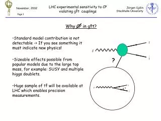
p 920 GeV e± 27.5 GeV Why a GTT? • Conceptual development path (1999) • How can the MVD be included in the trigger? • MVD participation in GFLT not feasible, readout latency too large. • Participation at GSLT possible, • but MVD track and vertex information poor due to low number planes. • Expand scope to include data from other tracking detectors - a Global Track Trigger: • Initially with the CTD - overlap with barrel detectors • Later with the STT - overlap with the wheel detectors • Trigger aims: • Initially implement an improved CTD-only trigger (z-vertex, tracks, Pt, invariant masses, etc.), then • add MVD hits to further improve trigger quantities, and • eventually extent the trigger to the forward region. C.Youngman / GTT group
CAL Front End Event buffers available Latency or time available Acceptrate Other Components 107 Hz CAL FLT 5s pipeline Global First Level Trigger synchronous clock driven CAL FCLR pipeline 4.4μs GFLT Accept/Reject 500Hz GFLT FCLR Abort Other Components 300Hz CAL SLT Event Buffers asynchronous event ordered Global Second Level Trigger 8-64 ~10ms GSLT Accept/Reject 60Hz Event Builder ~1000 asynchronous NOT event ordered Third Level Trigger ~100 ~1s 15Hz Offline Tape The ZEUS trigger • ZEUS trigger designed 1990 • First high rate pipelined system • Three trigger levels • GFLT first level • custom electrionics • ECL connections • all components are interfaced • GSLT second level • INMOS Transputer (TP) 25MHz • serial connections 2.5MB/s • subset of components connected • EVB • PC based • serial and network connections • distributes GSLT decision • all components connected • TLT third level • PC farm ~offline filter software • network connections C.Youngman / GTT group
CAL Front End Event buffers available Latency or time available Acceptrate Other Components 107 Hz CAL FLT 5s pipeline Global First Level Trigger synchronous clock driven CAL FCLR pipeline 4.4μs GFLT Accept/Reject 500Hz GFLT FCLR Abort Other Components 300Hz CAL SLT Event Buffers asynchronous event ordered Global Second Level Trigger 8-64 ~10ms GSLT Accept/Reject 60Hz Event Builder ~1000 asynchronous NOT event ordered Third Level Trigger ~100 ~1s 15Hz Offline Tape GTT driven trigger deadtime • Synchronization • GFLT control and data signals sent to and returned by the component's FLT sub-systems are locked to the HERA clock. • Deadtime • Occurs when the GFLT is disabled from issuing new accept triggers. • Components disable the GFLT trigger when a buffer full condition is about to occur; they reenable it when sufficient buffer space is available. • GTT latency (L) can give deadtime (lowest component event buffer count) (FCLR accept rate) If L > 7 / 300 = 23 ms the GTT will contribute to deadtime - this calculation is not accurate - the smallest possible latency must be targetted. L= C.Youngman / GTT group
CTD latency at GSLT mean = 13.6 ms tail < 44ms Run 54314 Fitting the GTT into the trigger Event buffers available Latency or time available Acceptrate CAL Front End • What the GTT has to do: • Components push data on GFLT accept and no FCLR abort to GTT • GTT computes decision • GTT sends decision to GSLT • Receive GSLT trigger decision • On GSLT accept send banks to EVB • Time requirements: • GTT decision latency at the GSLT must not be significantly worse than the CTD-SLT latency envelope 107 Hz Other Components CAL FLT pipeline 5s pipeline Global First Level Trigger CAL FCLR 4.4μs GFLT Accept/Reject 500Hz GTT GFLT FCLR Abort 300Hz Other Components CAL SLT Event Buffers 8-64 Global Second Level Trigger ~10ms GSLT Accept/Reject 60Hz Event Builder ~1000 Third Level Trigger ~100 ~1s 15Hz Offline Tape C.Youngman / GTT group
source: S.Cittolin 1992. ZEUS operational 1994. CTD SLT finalized 2002. GTT startup 2007. End Computing and communication trends • 1992 CTD-SLT implementation • CPU = 16 x 25 MHz TP network = 400 MHz • 10 kB data latency = 10 x 2.5 MB/s = 2.5 ms • 2000 GTT implementation • dual 1 GHz CPUs farm • 10 kB data latency = 10 x 10 MB/s = 0.25 ms • 1-2 switches • 2005 GTT implementation • dual 4 GHz CPUs farm • 10 kB data latency = 10 x 100 MB/s = 0.03 ms • many switches We have the 2000 implementation C.Youngman / GTT group
CTD or STT MVD OTHER COMPONENTS STRIP FIFO DATA PIPELINE DATA PIPELINE CLUSTER FIFO RESULT AND DATA BUFFERS LOCAL FLT GFLT DIGI- TIZED DATA BUFFER TP SPLITER INTER- FACE INTER- FACE GTT LOCAL SLT GSLT DECISION GFLT ACCEPT INTER- FACE GSLT GSLT DECISION GFLT ACCEPT EVB Component interfaces • CTD (and STT) • insert splitter TPs into component TP network to duplicate data stream • Send data to Nikhef 2TP VME modules in single VME crate • PPC VME CPU reads data via TPM • CPU sends complete event data to GTT • MVD • VME ADCs buffer data (3 crates) • On GFLT accept PPC VME CPU read data • CPU sends crate data to GTT For CTD and STT the Nikhef 2TP module marks the boundary between component and GTT. They have to boot their side executable. C.Youngman / GTT group
GTT hardware MVD readout CTD/STT interface • MVD readout • 3 Motorola MVME2400 450MHz • CTD/STT interfaces • NIKHEF-2TP VME-Transputer • Motorola MVME2400 450MHz • PC farm • 12 DELL PowerEdge 4400 Dual 1GHz • GTT/GSLT result interface • Motorola MVME2700 367MHz • GSLT/EVB trigger result interface • DELL PowerEdge 4400 Dual 1GHz • DELL PowerEdge 6450 Quad700 MHz • Network switches • 2 Intel Express 480T Fast/Giga 16 ports. • Thanks to Intel Corp. who provided switch and PowerEdge hardware via Yale grant. PC farm and switches GTT to GSLT interface EVB and GSLT decision C.Youngman / GTT group
GTT software • The GTT is the MVD SLT sub-system; there is no GTT on RCO just MVD ! • The GTT algorithm process running on each host contains the following threads: • MVD0 data source … reads MVD upper barrel cluster event data • MVD1 data source … reads MVD lower barrel cluster event data • MVD2 data source … reads MVD wheel cluster event data • CTD data source …... reads CTD axial and stereo event data • CTDZ data source …. reads CTD z-by-time event data • STT data source …… reads STT event data • Barrel algorithm …… uses MVD0, MVD1, CTD and CTDZ data for track finding • Forward algorithm … uses MVD2 and STT data for track finding • Timeout thread …….. forces a timeout result to be sent to the GSLT if 30-40ms exceeded • Main thread • Shutdown thread ….. receives shutdown signal • GSLT thread ………. receives GSLT trigger result, sending banks to EVB on accept. • A complete desciption of the GTT process software can be found on the GTT web page. • Note that the STT and Forward algorithms were run, 49375 thru 49858, they are not currently enabled and no results associated with them will be shown. C.Youngman / GTT group
Source event data sizes • Mean data size: • MVD0 = 1.3 kB • MVD1 = 1.4 kB • MVD2 = test run (usually < MVD0) • CTD = 4.1 kB • CTDZ = 1.1 kB • Event size data cutoff used to control latency: • CTD = CTDZ = 10kB • MVDx = 8kB (MVD used in GTT) • MVDx = 2kB (MVD not used in GTT) If the cutoff is exceeded no data is sent from the source, just a synchronization header. Runs 54588-89 C.Youngman / GTT group
Source event data sizes GSLT passthru sample • MVD cutoff issues: • the percentage of GSLT passthru events cut by MVD0+1 cutoff is, see table • the percentage (fraction x 100) of dijet events cut is similar, see plots. • noise in the MVD and background in HERA has to be controlled. • CTD cutoff issues: • Cutoff larger than max. seen, i.e. no cut. • ideal for GTT as no acceptance problems. smaller size = smaller latency Dijet sample C.Youngman / GTT group
Mean data latency: MVD0 = 0.7 ms MVD1 = 0.7 ms MVD2 = test run (usually < MVD0) CTD = 7.0 ms CTDZ = 4.4 ms CTD and CTDZ data are delayed by transfer times in TP networks. Arrival of source data with different delays reduces network contension. CTD and CTDZ latency will drive GTT latency. Source data latencies Latency (delay) of data at GTT after GFLT accept Runs 54588-89 C.Youngman / GTT group
Kinks in network transfer speeds are seen at 1 kB boundaries It's faster to send slightly more than N kB. Source transfer speed size dependent MVD < 1 kB = 3 MB/s > 1 kB = 10 MB/s (i.e. FastEthernet) CTD < 1 kB = 5 MB/s > 1 kB = 10 MB/s (i.e. FastEthernet) Not fully understood, but no problem Network transfer speeds Network transfer speed from interface to GTT Runs 54588-89 C.Youngman / GTT group
The barrel algorithm • Tracking in CTD is based on CTD-SLT algorithm, but includes all data including stereo data not available to the CTD-SLT - so it cannot be worse. • Track finding strategy used: • Pass 1 (improved CTD-SLT result) • axial segment finding • 2D axial track finding • 3D track finding with z-by-time space points • improve 3D track finding with stereo segments • calculate the z-vertex • Pass 2 (add MVD information to pass 1 tracks) • refit stereo segments using calculated z-vertex • recalculate vertex • refit tracks including MVD information • recalculate vertex Pass 2 is currently being implemented. Pass 1 and 2 results will be available to the GSLT. The following results will be a mixture of both !! C.Youngman / GTT group
Barrel reconstruction: clean event • Tracks: • yellow = GTT found track • red = VCTRAK CTD vertex track • blue = VCTRAK CTD non-vertex track Good agreement C.Youngman / GTT group
Barrel reconstruction: a not so clean event • Tracks: • yellow = GTT found track • red = VCTRAK CTD vertex track • blue = VCTRAK CTD non-vertex track Some tracks missed, but vertex found. C.Youngman / GTT group
Barrel reconstruction: a busy event • Tracks: • yellow = GTT found track • red = VCTRAK CTD vertex track • blue = VCTRAK CTD non-vertex track Tracks missed and different ones found, possibly two verticies - but probably OK. C.Youngman / GTT group
Barrel track finding efficiency • GTT track finding efficiency, compared to offline VCTRAK tracks, is higher for clean events. • Including MVD hits into the algorithm highlighted a number of bugs in the CTD only tracking, these have been corrected. clean events - pass 2 busy events - pass 2 C.Youngman / GTT group
Barrel primary z-vertex CTD only • Primary vertex uses CTD-SLT overlapping bin method. • bin track Z0 weighted by #stereo segments • use most probable bin as initial vertex • z-vertex from wt. Tracks within 9cm of initial vertex • Dijet sample • resolution 3.7 cm • efficiency ~95%; 2-3% a secondary vertex is found. • Addition of the MVD is expected to improve the vertex resolution to ~1.5 cm. • Improved methods are being finalized. Varying the vertex cut drives purity and background contamination. CTD only CTD only C.Youngman / GTT group
MVD latency at GSLT mean = 9.5 ms low tail exists Barrel performance • Barrel algorithm time requirement • Data decoding and preparation ~ 0.2 ms • Processing: mean ~1ms, max < 10 ms • GTT latency at the GSLT is acceptable • 9.5 ms mean is better than the CTD's 13.6 ms • tail is slightly longer • adding Pass 2 is not expected to change this • GTT latency driven by data source latency C.Youngman / GTT group
GTSBEV bank 1st row is Pass 1 result 2nd row is Pass 2 result (if present) trigger quantities: Primary vertex Number of tracks found Pt of highest 2 tracks Pt sum of vertex tracks Background word J-psi mass D0 mass Flag3 contains important control bits: timeout flag, etc. GTDSEV bank Precut event data sizes Both GTSBEV and GTDSEV banks are written offline for use in trigger checks. It is likely that more information will be added. Barrel results sent to the GSLT C.Youngman / GTT group
Impact on GSLT trigger • Of 72 active trigger slots at GSLT (recent 05_v72) • 12 use GTT tracking information ( Zvtx, Nvtxtrk, Ntrk, Pt, …) • 24 use GTT supplied input component datasize cutoffs • Precise quantification difficult due to slot duplication and multiple similar slot definitions, plus unclear usage in final analysis. • Physics group usage • HFL: HFG01 (copy of HFL1), HFG02 (copy of HFL3), HFG05 (copy of HFL5 feedback?), HFG07 (copy of HFL7), and HFGB1 (lower rate HFL1) • EXO: EXG07 (beamgas testbed feedback?) • MU: MUG05 (MU01 at high lumi) • QCD: HPG13 thru HPG17 (test triggers?) • Conclusions: • Currently there is a lot of activity on adding the GTT by the physics groups. • As the GTT barrel result is much better than the CTD-SLT the later will be disabled after the shutdown. C.Youngman / GTT group
DQM, simulation, implementing new versions. • Standard GSLT passthru and physics input data sets available for testing new versions on and offline. • Libraries available for ZGANA/czar trigger simulation. • GTT DQM plots included in CTD tcbol web page. These are currently being improved. Well checked new version can be introduced without errors. The stability of GTT results can be monitored. C.Youngman / GTT group
Constants • The effect on the GTT of changing CTD contants (drift velocity, etc.) has been investigated • A web tool is now available which allows the database to be modified by the CTD expert when significant changes are found. C.Youngman / GTT group
Acknowledgements • Who is currently working on what: • N.Copola - GSLT trigger • M.Sutton - DQM, simulation, barrel Pass1 • V.Roberfroid - CVS, barrel Pass2 • C.Youngman - GTT software • B.Straub - trigger implementation, performance measurement • J.Ferrando - J/psi • Who has worked on what: • B.Dunne - J/psi • A.Polini - source interfaces • M.Bell - vertexing, performance measurements • P.Alfrey - trigger implementation, performance measurments • D.Gladkov - forward algorithm • S.Dhawan - hardware • R.Hall-Wilton - trigger implementation C.Youngman / GTT group
Integrating the STT? Latency: T(first frame at GTT) - T(GFLT accept) • Data size and latency issues • tests in 2003 showed that the data size, and hence latency at the GTT was often large. This has to be addressed by the STT group. • The potency of a forward trigger at the GSLT also needs (re)evaluating • Is enough time and effort available? • It has taken nearly 12 months to get a baseline CTD+MVD algorithm available. latency (ms) CTD data size (kB) latency (ms) STT data size (kB) C.Youngman / GTT group