Download
1 / 1
10 likes | 282 Views

E N D
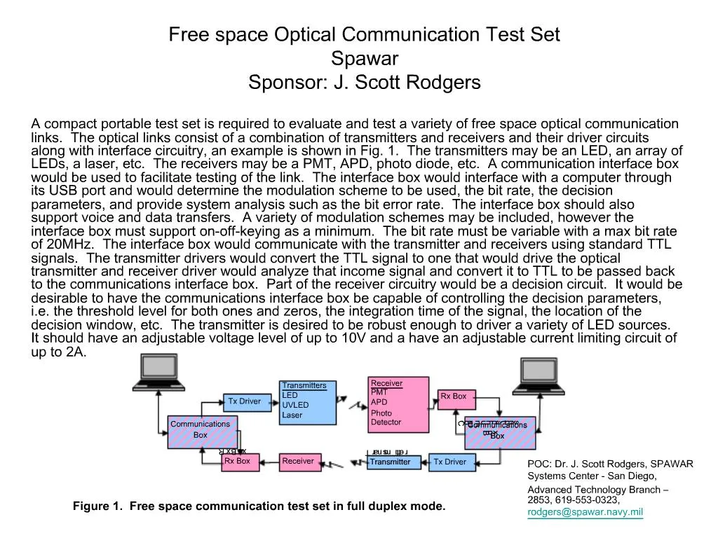
1. Free space Optical Communication Test Set Spawar Sponsor: J. Scott Rodgers A compact portable test set is required to evaluate and test a variety of free space optical communication links. The optical links consist of a combination of transmitters and receivers and their driver circuits along with interface circuitry, an example is shown in Fig. 1. The transmitters may be an LED, an array of LEDs, a laser, etc. The receivers may be a PMT, APD, photo diode, etc. A communication interface box would be used to facilitate testing of the link. The interface box would interface with a computer through its USB port and would determine the modulation scheme to be used, the bit rate, the decision parameters, and provide system analysis such as the bit error rate. The interface box should also support voice and data transfers. A variety of modulation schemes may be included, however the interface box must support on-off-keying as a minimum. The bit rate must be variable with a max bit rate of 20MHz. The interface box would communicate with the transmitter and receivers using standard TTL signals. The transmitter drivers would convert the TTL signal to one that would drive the optical transmitter and receiver driver would analyze that income signal and convert it to TTL to be passed back to the communications interface box. Part of the receiver circuitry would be a decision circuit. It would be desirable to have the communications interface box be capable of controlling the decision parameters, i.e. the threshold level for both ones and zeros, the integration time of the signal, the location of the decision window, etc. The transmitter is desired to be robust enough to driver a variety of LED sources. It should have an adjustable voltage level of up to 10V and a have an adjustable current limiting circuit of up to 2A.