Download
1 / 72
1.99k likes | 3.3k Views
Spanning Tree Protocol. Module 3. STP allows L2 devices to communicate with each other to discover physical loops in the network. STP specifies an algorithm that L2 devices can use to create a loop-free logical topology.

E N D
Spanning Tree Protocol Module 3
STP allows L2 devices to communicate with each other to discover physical loops in the network. STP specifies an algorithm that L2 devices can use to create a loop-free logical topology. STP creates a tree structure of loop-free leaves and branches that spans the entire Layer 2 network. Spanning Tree Protocol (STP)
Broadcasts and Layer 2 loops can be a dangerous combination. Ethernet frames have no TTL field After an Ethernet frame starts to loop, it will probably continue until someone shuts off one of the switches or breaks a link. L2 Loops
Where’s Host B? FLOOD Where’s Host B? FLOOD Where’s Host B? FLOOD Where’s Host B? FLOOD L2 Loops - Flooded unicast frames And the floods continue Removed from the network
The purpose of STP is to avoid and eliminate loops in the network by negotiating a loop-free path through a root bridge. STP determines where the are loops and blocks links that are redundant. Ensures that there will be only one active path to every destination. STP Prevents Loops
STP executes an algorithm called STA. STA chooses a reference point, called a root bridge, and then determines the available paths to that reference point. If more than two paths exists, STA picks the best path and blocks the rest Spanning Tree Algorithm
Two-key STP Concepts • STP calculations make extensive use of two key concepts in creating a loop-free topology: • Bridge ID • Path Cost
Bridge ID (BID) is used to identify each bridge/switch. • The BID is used in determining the center of the network, in respect to STP, known as the root bridge.
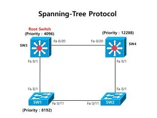
Used to elect a root bridge • Lowest Bridge ID is the root. • If all devices have the same priority, the bridge with the lowest MAC address becomes the root bridge.
IEEE modified the most to use a non-linear scale with the new values of: 4 Mbps 250 (cost) 10 Mbps 100 (cost) 16 Mbps 62 (cost) 45 Mbps 39 (cost) 100 Mbps 19 (cost) 155 Mbps 14 (cost) 622 Mbps 6 (cost) 1 Gbps 4 (cost) 10 Gbps 2 (cost) Path Cost
BID and Path Cost are used to develop a loop-free topology . But first the Four-Step STP Decision Sequence BID and Path Cost
When creating a loop-free topology, STP uses: Four-Step decision Sequence Step 1 - Lowest BID Step 2 - Lowest Path Cost to Root Bridge Step 3 - Lowest Sender BID Step 4 - Lowest Port ID Bridges use Configuration BPDUs during this four-step process. Four-Step STP Decision Sequence
BPDU key concepts: Bridges save a copy of only the best BPDU seen on every port. When making this evaluation, it considers all of the BPDUs received on the port, as well as the BPDU that would be sent on that port. As every BPDU arrives, it is checked against this four-step sequence to see if it is more attractive (lower in value) than the existing BPDU saved for that port. Only the lowest value BPDU is saved. Bridges send configuration BPDUs until a more attractive BPDU is received. Okay, lets see how this is used... Four-Step STP Decision Sequence
The STP algorithm uses three simple steps to converge on a loop-free topology: STP Convergence Step 1 Elect one Root Bridge Step 2 Elect Root Ports Step 3 Elect Designated Ports Three Steps of Initial STP Convergence
STP ConvergenceStep 1 Elect one Root BridgeStep 2 Elect Root PortsStep 3 Elect Designated Ports
When the network first starts, all bridges are announcing a chaotic mix of BPDUs. All bridges immediately begin applying the four-step sequence decision process. Switches need to elect a single Root Bridge. Switch with the lowest BID wins! Note: “highest priority” is the “lowest” BID value. This is known as the “Root War.” STP ConvergenceStep 1 Elect one Root Bridge
STP ConvergenceStep 1 Elect one Root Bridge Cat-A has the lowest Bridge MAC Address, so it wins the Root War! All 3 switches have the same default Bridge Priority value of 32,768
STP ConvergenceStep 1 Elect one Root Bridge Its all done with BPDUs!
At the beginning, all bridges assume they are the center of the universe and declare themselves as the Root Bridge, by placing its own BID in the Root BID field of the BPDU. STP ConvergenceStep 1 Elect one Root Bridge
Once all of the switches see that Cat-A has the lowest BID, they are all in agreement that Cat-A is the Root Bridge. STP ConvergenceStep 1 Elect one Root Bridge
STP ConvergenceStep 1 Elect one Root BridgeStep 2 Elect Root PortsStep 3 Elect Designated Ports
A bridge’s Root Port is the port closest to the Root Bridge. Bridges use the cost to determine closeness. Every non-Root Bridge will select one Root Port! Bridges track the Root Path Cost, the cumulative cost of all links to the Root Bridge. STP ConvergenceStep 2 Elect Root Ports
BPDU Cost=0 BPDU Cost=0 Step 1 • Cat-A sends out BPDUs, containing a Root Path Cost of 0. • Cat-B receives these BPDUs and adds the Path Cost of Port 1/1 to the Root Path Cost contained in the BPDU. Step 2 • Cat-B add Root Path Cost 0 PLUS its Port 1/1 cost of 19 = 19 BPDU Cost=0+19=19 BPDU Cost=0+19=19
BPDU Cost=0 BPDU Cost=0 Step 3 • Cat-B uses this value of 19 internally and sends BPDUs with a Root Path Cost of 19 out Port 1/2. Step 4 • Cat-C receives the BPDU from Cat-B, and increased the Root Path Cost to 38 (19+19). (Same with Cat-C sending to Cat-B.) BPDU Cost=19 BPDU Cost=19 BPDU Cost=19 BPDU Cost=19 BPDU Cost=38 (19=19) BPDU Cost=38 (19=19)
BPDU Cost=0 BPDU Cost=0 Step 5 • Cat-B calculates that it can reach the Root Bridge at a cost of 19 via Port 1/1 as opposed to a cost of 38 via Port 1/2. • Port 1/1 becomes the Root Port for Cat-B, the port closest to the Root Bridge. • Cat-C goes through a similar calculation. Note: Both Cat-B:1/2 and Cat-C:1/2 save the best BPDU of 19 (its own). BPDU Cost=19 BPDU Cost=19 Root Port Root Port BPDU Cost=38 (19=19) BPDU Cost=38 (19=19)
STP ConvergenceStep 1 Elect one Root BridgeStep 2 Elect Root PortsStep 3 Elect Designated Ports
A Designated Port functions as the single bridge port that both sends and receives traffic to and from that segment and the Root Bridge. Each segment in a bridged network has one Designated Port, chosen based on cumulative Root Path Cost to the Root Bridge. The switch containing the Designated Port is referred to as the Designated Bridge for that segment. To locate Designated Ports, lets take a look at each segment. Root Path Cost, the cumulative cost of all links to the Root Bridge. STP ConvergenceStep 3 Elect Designated Ports
Root Path Cost = 0 Root Path Cost = 0 Segment 1 Segment 2 • Segment 1: Cat-A:1/1 has a Root Path Cost = 0 (after all it is the Root Bridge) and Cat-B:1/1 has a Root Path Cost = 19. • Segment 2: Cat-A:1/2 has a Root Path Cost = 0 (after all it is the Root Bridge) and Cat-C:1/1 has a Root Path Cost = 19. • Segment 3: Cat-B:1/2 has a Root Path Cost = 19 and Cat-C:1/2 has a Root Path Cost = 19. It’s a tie! Root Path Cost = 19 Root Path Cost = 19 Root Port Root Port Root Path Cost = 19 Root Path Cost = 19 Segment 3
Root Path Cost = 0 Root Path Cost = 0 Segment 1 Segment 2 Designated Port Designated Port Segment 1 • Because Cat-A:1/1 has the lower Root Path Cost it becomes the Designate Port for Segment 1. Segment 2 • Because Cat-A:1/2 has the lower Root Path Cost it becomes the Designate Port for Segment 2. Root Path Cost = 19 Root Path Cost = 19 Root Port Root Port Root Path Cost = 19 Root Path Cost = 19 Segment 3
Root Path Cost = 0 Root Path Cost = 0 Segment 1 Segment 2 Designated Port Designated Port Segment 3 • Both Cat-B and Cat-C have a Root Path Cost of 19, a tie! • When faced with a tie (or any other determination) STP always uses the four-step decision process: 1. Lowest Root BID; 2. Lowest Path Cost to Root Bridge; 3. Lowest Sender BID; 4. Lowest Port ID Root Path Cost = 19 Root Path Cost = 19 Root Port Root Port Root Path Cost = 19 Root Path Cost = 19 Segment 3
Root Path Cost = 0 Root Path Cost = 0 Segment 1 Segment 2 Designated Port Designated Port Segment 3 (continued) • 1) All three switches agree that Cat-A is the Root Bridge, so this is a tie. • 2) Root Path Cost for both is 19, also a tie. • 3) The sender’s BID is lower on Cat-B, than Cat-C, so Cat-B:1/2 becomes the Designated Port for Segment 3. • Cat-C:1/2 therefore becomes the non-Designated Port for Segment 3. Root Path Cost = 19 Root Path Cost = 19 Root Port Root Port 32,768.CC-CC-CC-CC-CC-CC 32,768.BB-BB-BB-BB-BB-BB Root Path Cost = 19 Root Path Cost = 19 Designated Port Segment 3 Non-Designated Port
Port Cost/Port ID 0/2 0/1 • If the path cost and bridge IDs are equal (as in the case of parallel links), the switch goes to the port priority as a tiebreaker. • Lowest port priority wins (all ports set to 128). • You can set the priority from 0 – 255. • If all ports have the same priority, the port with the lowest port number forwards frames. Assume path cost and port priorities are default (128). Port ID used in this case. Port 0/1 would forward because it’s the lowest.
Recall that switches go through three steps for their initial convergence: STP ConvergenceStep 1 Elect one Root BridgeStep 2 Elect Root PortsStep 3 Elect Designated Ports Also, all STP decisions are based on a the following predetermined sequence: Four-Step decision Sequence Step 1 - Lowest BID Step 2 - Lowest Path Cost to Root Bridge Step 3 - Lowest Sender BID Step 4 - Lowest Port ID STP ConvergenceRecap
Blocked: All ports start in blocked mode in order to prevent the bridge from creating a bridging loop. Port are listening (receiving) BPDUs. No user data is being passed. The port stays in a blocked state if Spanning Tree determines that there is a better path to the root bridge. May take a port up to 20 seconds to transition out of this state (max age). Spanning-Tree Port States
Listen: The port transitions from the blocked state to the listen state Attempts to learn whether there are any other paths to the root bridge Listens to frames Port is not sending or receive user data Listens for a period of time called the forward delay (default 15 seconds). Ports that lose the Designated Port election become non-Designated Ports and drop back to Blocking state. Spanning-Tree Port States
Learn: The learn state is very similar to the listen state, except that the port can add information it has learned to its address table. Adds addresses to MAC Address Table Still not allowed to send or receive user data Learns for a period of time called the forward delay (default 15 seconds) Spanning-Tree Port States
Forward: The port can send and receive user data. A port is placed in the forwarding state if: There are no redundant links or It is determined that it has the best path to the root Spanning-Tree Port States
Spanning-Tree Port States • Disabled: The port is shutdown.
A root port for each switch and a designated port for each segment is selected. These ports provide the best path from the switch to the root switch (usually the lowest-cost path). These ports are put in the forwarding mode. Ports that will not be forwarding are placed in the blocked state. These ports will continue to send and receive BPDU information but will not be allowed to send or receive data. Results of BPDU exchange
Configuring STP • By default, STP is enabled for every port on the switch. • If for some reason STP has been disabled, you can reenable it.
Enable Spanning Tree (Enabled by default) Switch(config)# spantree vlan-list Configure STP timers Switch(config)# spanning-tree [vlanvlan-list] [hello-timeseconds] *Default = 2 seconds Switch(config)# spanning-tree [vlanvlan-list] [forward-timeseconds] *Default = 15 seconds Switch(config)# spanning-tree [vlanvlan-list] [max-ageseconds] *Default = 20 seconds Configuring STP
Configuring Port Cost (to tweak Path Cost) Switch(config-if) spanning-tree [vlan vlan-list] cost cost(1-65,535) (lower wins) Configuring Bridge Priority (to tweak BID & root election) Switch(config)# spanning-tree [vlan vlan-list] priority priority *Default = 32,768 (0=65,535) (lower wins) Configuring STP
Configuring Port Priority Switch(config)# spanning-tree [vlan vlan-list] priority priority *Default = 128 (0-255) The port with the lowest priority value forwards frames for that vlan. This command can be very useful for load balancing vlans across multiple paths. Configuring STP
Verifying STP Switch# show spanning-tree [vlan] Switch# show spanning-treemod/num