Download
1 / 12
120 likes | 304 Views
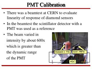
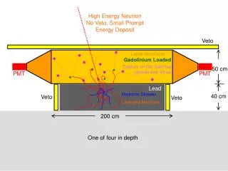
How to count PMT pulses. Victor Kornilov Sternberg astronomical institute I count photons 25 years. Classical scheme of a photon counting. Pulses from PMT A~3mV, I<10 m A Pulses from amplifier to counter A~3V, I~60mA. Problems. Both signals have the same frequency characteristics

E N D
How to count PMT pulses Victor Kornilov Sternberg astronomical institute I count photons 25 years.
Classical scheme of a photon counting Pulses from PMT A~3mV, I<10mA Pulses from amplifier to counter A~3V, I~60mA
Problems • Both signals have the same frequency characteristics • And output pulses influent at input pulses • Difficulties are enlarged for pulses < 30ns • Ground problem, External noise Evident solution: To count pulses near amplifier, in this case a system of data transmission into host computer needed. (Hamamatsu and ETL produce a photometric modules with RS232 interface)
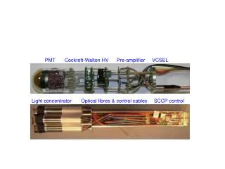
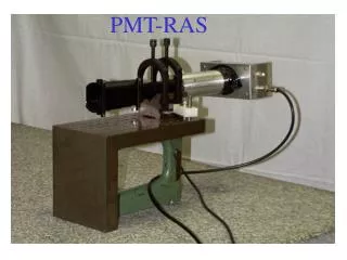
Devices control and Data acquisition • Physical layer 1 – RS485 (Recommended Standard) interface • Physical layer 2 – Inexpensive components (RISC mcontrollers) • Logical layer 1 - Exchange by bytes united in addressed packets, terminated by special signals, CRC • Logical layer 2 – Nonsymmetrical structure, exchange via host only, passive, active, induced transaction • Logical layer 3 – compact commands, data packets, direct access to module parameters, containers • Interface boards, converters, drivers, software. • We use this unnamed system 5 years (described in MASS documentation).
Transaction modes • 1 - Command (reply signal only) • 2 – Data request • 3 – Active data transmission
Properties of the RS485 • Communicate multiple nodes bi-directionally over a single twisted pair. • Excellent noise rejection (differential balanced) • High data rate with long cable • General robustness.
Considerations of RS485 • Configuration • Termination and stubs • Data rate vs cable length • Cabling • Fail-safe biasing • Grounding and shielding Useful papers: www.national.com, Application notes www.bb-europe.com, RS-422 and RS-485 Application Note
Amplifier-discriminator • Preamplifier - transimpendance SA5205, band 600MHz, K=9 (Philips) • Pulse discrimination – Ultra fast comparator AD8611, 4ns • Digital control of discrimination level • Noise <200 mV • Deadtime with Hamamatsu R647 – 17ns, with R7400 ~10ns Permits to measure fluxes up to 10 Mp/s (if counter permits too…)
Counter, control and exchange • Pre-counter 74HC(T)4520, fmax=60MHz • Kernel - m controller ATMega8-16 • 2 channels with 16 bits, may be 24 bits • Hardware generation of integration strobe • In system reprogramming of m-programm • PMT current control • Exchange rate up to 2Mbit/s