Download
1 / 42
420 likes | 605 Views
Development of Design and Engineering Engines to Support Multidisciplinary Design and Analysis of Aircraft. Presented by G. La Rocca G.LaRocca@LR.TUDelft.NL . The challenges for the next 20 years of aviation. According to ACARE and NASA the aircraft of the future will have to be: Faster

E N D
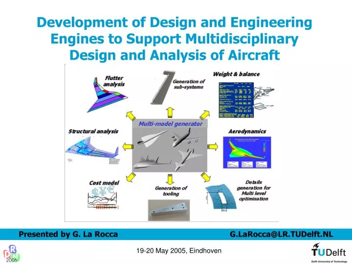
Development of Design and Engineering Engines to Support Multidisciplinary Design and Analysis of Aircraft Presented by G. La Rocca G.LaRocca@LR.TUDelft.NL 19-20 May 2005, Eindhoven
The challenges for the next 20 years of aviation • According to ACARE and NASA the aircraft of the future will have to be: • Faster • with higher payload capacity • Safer • Cleaner • Quieter • …..different? • AFFORDABLE! • How to achieve that in the current situation? • Less economic and intellectual resources available • Engineers have less experience from past programs • Increased mobility of knowledge workers • Globalization of the market • Projects run by teams scattered over the globe….. 19-20 May 2005, Eindhoven
Development of improved methodologies to allow thoroughly and efficient exploration of the design space • Reduce the time wasted in repetitive and routine activities • Give more space to creative design • Focus on methodologies to capture and efficiently reuse designers’ knowledge 19-20 May 2005, Eindhoven
Start Start MULTI MULTI - - MODEL GENERATOR (MMG) MODEL GENERATOR (MMG) Requirements Requirements Product Model Product Model INITIATOR INITIATOR Calculation of Calculation of Report writers Report writers Discipline #2 Discipline #2 Discipline #n Discipline #n Discipline #1 Discipline #1 product model product model parameter values parameter values CONVERGER CONVERGER Report files Report files & & EVALUATOR EVALUATOR Check of analysis Check of analysis results on: results on: 1) convergence 1) convergence 2) compliance with 2) compliance with requirements requirements Analysis tools Analysis tools Discipline #n Discipline #n Discipline #2 Discipline #2 Discipline #1 Discipline #1 no no 1 1 yes yes no no 2 2 yes yes Design solution Design solution Data files Data files End End Definition of Design and Engineering Engine (DEE) A DEE is an advanced design system to support and accelerate the design process of complex products through the automation of non-creative and repetitive design activities. A DEE consists of a multi-disciplinary collection of design and analysis tools, which are able to automatically interface each other and exchange data and information generated by their internal processes. 19-20 May 2005, Eindhoven
Start Start MULTI MULTI - - MODEL GENERATOR (MMG) MODEL GENERATOR (MMG) Requirements Requirements Product Model Product Model INITIATOR INITIATOR Calculation of Calculation of Report writers Report writers Discipline #n Discipline #n Discipline #2 Discipline #2 Discipline #1 Discipline #1 product model product model parameter values parameter values CONVERGER CONVERGER Report files Report files & & EVALUATOR EVALUATOR Check of analysis Check of analysis results on: results on: 1) convergence 1) convergence 2) compliance with 2) compliance with requirements requirements Analysis tools Analysis tools Discipline #2 Discipline #2 Discipline #n Discipline #n Discipline #1 Discipline #1 no no 1 1 yes yes no no 2 2 yes yes Design solution Design solution Data files Data files End End Paradigm of a Design and Engineering Engine (DEE) The Multi Model Generator (MMG) 19-20 May 2005, Eindhoven
Start Start MULTI MULTI - - MODEL GENERATOR (MMG) MODEL GENERATOR (MMG) Requirements Requirements Product Model Product Model INITIATOR INITIATOR Calculation of Calculation of Report writers Report writers Discipline #n Discipline #n Discipline #2 Discipline #2 Discipline #1 Discipline #1 product model product model parameter values parameter values CONVERGER CONVERGER Report files Report files & & EVALUATOR EVALUATOR Check of analysis Check of analysis results on: results on: 1) convergence 1) convergence 2) compliance with 2) compliance with requirements requirements Analysis tools Analysis tools Discipline #2 Discipline #2 Discipline #n Discipline #n Discipline #1 Discipline #1 no no 1 1 yes yes no no 2 2 yes yes Design solution Design solution Data files Data files End End Paradigm of a Design and Engineering Engine (DEE) The product model 19-20 May 2005, Eindhoven
Start Start MULTI MULTI - - MODEL GENERATOR (MMG) MODEL GENERATOR (MMG) Requirements Requirements Product Model Product Model INITIATOR INITIATOR Calculation of Calculation of Report writers Report writers Discipline #n Discipline #n Discipline #2 Discipline #2 Discipline #1 Discipline #1 product model product model parameter values parameter values CONVERGER CONVERGER Report files Report files & & EVALUATOR EVALUATOR Check of analysis Check of analysis results on: results on: 1) convergence 1) convergence 2) compliance with 2) compliance with requirements requirements Analysis tools Analysis tools Discipline #2 Discipline #2 Discipline #n Discipline #n Discipline #1 Discipline #1 no no 1 1 yes yes no no 2 2 yes yes Design solution Design solution Data files Data files End End Paradigm of a Design and Engineering Engine (DEE) The reports writers 19-20 May 2005, Eindhoven
Development of a Design and Engineering Engine (DEE) The extent of achievable automation for the repetitive design activities mainly depends on: - Capability of the DEE components to interface each other and exchange data and information (development required at framework level) - Quality and level of maturity of data and information generated by the DEE components (development required at tools level) 19-20 May 2005, Eindhoven
Functional requirements A.I. Y Y Y Y Y Y Y Y Eval Eval Eval Eval Eval Eval Eval Eval first spar first spar first spar first spar first spar first spar first spar first spar ? ? ? ? ? ? ? ? N N N N N N N N Y Y Y Y Y Y Y Y ? ? ? ? ? ? ? ? Rib Rib Rib Rib Rib Rib Rib Rib = = = = = = = = ‘FD ‘FD ‘FD ‘FD ‘FD ‘FD ‘FD ‘FD spar spar spar spar spar spar spar spar n n n n n n n n N N N N N N N N Point at root Point at root Point at root Point at root Point at root Point at root Point at root Point at root Engineered design Knowledge Based Engineering (KBE): a technological implementation of the Knowledge Management vision for the engineering business Functional Functional Functional Functional Functional Functional requirements requirements requirements requirements requirements requirements A.I. A.I. Knowledge Knowledge Knowledge INPUTS INPUTS INPUTS INPUTS Based Based Based Size, material, positioning …. Size, material, positioning …. Size, material, positioning …. Size, material, positioning …. Engineering Engineering Engineering GENERATIVE MODEL GENERATIVE MODEL GENERATIVE MODEL GENERATIVE MODEL Product Structure Product Structure Product Structure Product Structure Design Standards Design Standards Design Standards Design Standards Material Characteristic Material Characteristic Material Characteristic Material Characteristic Manufacturing Constrain Manufacturing Constraints Manufacturing Constrain Manufacturing Constraints CAD CAD CAD KBE technology integrates Artificial Intelligence and Computer Aided Design to produce computerized applications able to capture and re-use efficiently and effectively the engineering design knowledge of the organization Engineering Analysis Engineering Analysis Engineering Analysis Engineering Analysis …….. …….. …….. …….. OUTPUTS OUTPUTS OUTPUTS OUTPUTS Drawings, 3 Drawings, 3 Drawings, 3 Drawings, 3 - - - - D Models, 2 D Models, 2 D Models, 2 D Models, 2 - - - - D Models, D Models, D Models, D Models, Bills of material, Tool Design …. Bills of material, Tool Design …. Bills of material, Tool Design …. Bills of material, Tool Design …. Engineered Engineered design design 19-20 May 2005, Eindhoven
Wing-Trunk Fuselage-Trunk Engine part Connection element Definition of the High Level Primitives (HLPs) • Wing-Trunk parameters set • - Type of airfoil (from a library) • - Amount of airfoils • - Positioning of airfoils • Thickness of airfoils • Reference axis • - Chords’ length • - Span • - Dihedral angle • - Sweep angle • Twist angle • …… 19-20 May 2005, Eindhoven
Wing-Trunk Fuselage-Trunk Engine part Connection element The building block approach 19-20 May 2005, Eindhoven
Wing-Trunk Fuselage-Trunk Engine part Connection element The building block approach 19-20 May 2005, Eindhoven
Wing-Trunk Fuselage-Trunk Engine part Connection element The building block approach 19-20 May 2005, Eindhoven
Wing-Trunk Fuselage-Trunk Engine part Connection element The building block approach 19-20 May 2005, Eindhoven
Wing-Trunk Fuselage-Trunk Engine part Connection element The building block approach 19-20 May 2005, Eindhoven
Wing-Trunk Fuselage-Trunk Engine part Connection element Generation of many aircraft configurations 19-20 May 2005, Eindhoven
Wing-Trunk Fuselage-Trunk Engine part Connection element Generation of variants of one configuration 19-20 May 2005, Eindhoven
Wing-Trunk Fuselage-Trunk Engine part Connection element Generation of variants of one configuration 19-20 May 2005, Eindhoven
Leading edge Upper wing-box panel Ribs Rear spar Front spar Lower wing-box panel Trailing edge Development of the structural models The MMG automatically generates the geometry of the structural elements inside each primitive. if the aircraft outer shape changes…. • The structure is: • parametrically defined • tailored to the outer surface 19-20 May 2005, Eindhoven
Leading edge Upper wing-box panel Ribs Rear spar Front spar Lower wing-box panel Trailing edge Development of the structural models The MMG automatically generates the geometry of the structural elements inside each primitive. … the internal structure has to follow! • The structure is: • parametrically defined • tailored to the outer surface 19-20 May 2005, Eindhoven
MMG links with the analysis tools: How different experts look at the same product 19-20 May 2005, Eindhoven
Models generation for aerodynamics tools (HF/LF) ICAD environment Aero analysis environment 19-20 May 2005, Eindhoven
Non Structural Items masses: Weight & C.G. location table item Mass_(kg) X_cg Y_cg Z_cg GROUP_FUSELAGE_(left_half) TED_1_(half) 107.4 44973.1 -1250.3 1250.1 …….. ANTI-ICING-SYSTEM 240.0 12755.8 -6368.1 490.0 OPERATIONAL_ITEMS_(half) 157.5 3000.0 0.0 0.0 CABIN_ARRANGEMENTS_(half) 40.0 3000.0 0.0 0.0 FLUIDS_(half) 3.0 3000.0 0.0 0.0 GROUP_WING_(left_half) TED_4_(iw_ins) 309.1 43256.9 -15067.4 2543.5 TED_5_(iw_out) 292.0 41879.3 -20362.6 2256.1 ……. ANTI-ICING-SYSTEM_(ow) 402.0 40304.5 -31062.3 1671.6 GROUP_WINGLET_(left_half) RUDDER 174.5 49785.9 -39394.7 4990.1 ANTI-ICING-SYSTEM_(wl) 80.0 47962.0 -39490.0 5531.1 GROUP_PROPULSION_(left_half) CENTER_ENGINE_(half) 3751.2 43758.0 0.0 4142.9 CENT_ENG_.. 980.7 43758.0 0.0 2185.7 LEFT_ENGINE 7502.3 39750.0 -7501.0 5410.5 LEFT_ENG_STRUC….. 1961.3 39750.0 -7501.0 3453.2 GROUP_LANDING_GEARS_(left_half) NOSE_LANDING_RETRACTED_(half) 594.0 3500.0 0.0 -1298.6 INNER_LANDING_RETRACTED 3415.7 33984.0 -3991.0 -87.1 OUTER_LANDING_RETRACTED 3415.7 33984.0 -7501.0 381.5 Lumped mass representation 19-20 May 2005, Eindhoven
Non-Structural Masses connectivity The MMG automatically detects the NSM-items to be attached to the various mainframe parts. This connectivity information is stored as an attribute of the given structure part. 19-20 May 2005, Eindhoven
Automatic surfaces fragmentation in meshable elements The MMG automatically performs the fragmentation of the aircraft surfaces to ease preprocessing activities required for the FEM analysis. Skins, spars and ribs are automatically cut along their intersection lines in order to produce ALWAYS a set of ready-to-meshed surface patches. Skin fragments TE fragments Segmentation procedure based on FEM-experts best practice. Automatic detection of non-meshable surfaces and selection of best extra cutting-procedure. LE fragments Ribs fragments Spars fragments 19-20 May 2005, Eindhoven
Integration of the ICAD MMG with the FE tools KBE environment FEM environment FEM-Tables surface_ID_number 2000023 Isoparametric? T membership INNER-WING-INSIDE type QUAD-SEGMENT design_variable_group 2010203 material AL_ZI_PLATE thickness_(mm) 6.0 Attach_non_struc_mass DE-ICE_SYSTEM Other information …………. number_of_nodes 4 node_ID X Y Z 92 49542.0 -39936.5 8381.3 93 49454.4 -39895.0 8173.1 94 49871.0 -39859.8 8061.9 95 49962.0 -39926.1 8383.2 Meshable surfaces 19-20 May 2005, Eindhoven
Sub-models generation for Multi-Level analysis Analysis of details should reflect all the changes in the global model Details generation should not affect the complexity of the global model 19-20 May 2005, Eindhoven
Generation of components models for manufacturing feasibility study, tooling design and cost analysis Examples of movable surfaces moulds models and tooling 19-20 May 2005, Eindhoven
Role of the MMG in the MOB project Multi disciplinary design and Optimisation of Blended wing body aircraft SAAB, NLR NLR, Cranfield University TU Delft NLR, BAe System DLR NLR, EADS, BAe System Siegen University 19-20 May 2005, Eindhoven
Start Start MULTI MULTI - - MODEL GENERATOR (MMG) MODEL GENERATOR (MMG) Requirements Requirements Product Model Product Model INITIATOR INITIATOR Calculation of Calculation of Report writers Report writers Discipline #2 Discipline #2 Discipline #n Discipline #n Discipline #1 Discipline #1 product model product model parameter values parameter values CONVERGER CONVERGER Report files Report files & & EVALUATOR EVALUATOR Check of analysis Check of analysis results on: results on: 1) convergence 1) convergence 2) compliance with 2) compliance with requirements requirements Analysis tools Analysis tools Discipline #n Discipline #n Discipline #2 Discipline #2 Discipline #1 Discipline #1 no no 1 1 yes yes no no 2 2 yes yes Design solution Design solution Data files Data files End End The Design and Engineering Engine (DEE) Framework 19-20 May 2005, Eindhoven
Start Start MULTI MULTI - - MODEL GENERATOR (MMG) MODEL GENERATOR (MMG) Requirements Requirements Product Model Product Model INITIATOR INITIATOR Calculation of Calculation of Report writers Report writers Discipline #2 Discipline #2 Discipline #n Discipline #n Discipline #1 Discipline #1 product model product model parameter values parameter values CONVERGER CONVERGER Report files Report files & & EVALUATOR EVALUATOR Check of analysis Check of analysis results on: results on: 1) convergence 1) convergence 2) compliance with 2) compliance with requirements requirements Analysis tools Analysis tools Discipline #n Discipline #n Discipline #2 Discipline #2 Discipline #1 Discipline #1 no no 1 1 yes yes no no 2 2 yes yes Design solution Design solution Data files Data files End End The Design and Engineering Engine (DEE) Framework 19-20 May 2005, Eindhoven
Design and Engineering Engine Framework DEE can be seen as a Integrated Product Team (IPT) or Design Built Team (DBT). Analogue to human group co-operation Detached capabilities combined through in-direct co-operation. SOFTWARE FRAMEWORK FOR DEEs 19-20 May 2005, Eindhoven
Four actors: Specialist (Disciplinary Tools) Integrator (Helper Agent, DEEF development) Operator (Operation of DEE) Maintainer (Operation of DEEF) Management functions Facilitating functions SOFTWARE FRAMEWORK FOR DEEs • Four Functions: • Resource Management • Resource Interfacing • Process Execution Support • Information Flow Control 19-20 May 2005, Eindhoven
Actors Tool development by Specialist. Offline testing Batch operation Agent/DEEF development by Integrator Operation of DEE by an Operator Maintenance of the DEEF by Maintainer SOFTWARE FRAMEWORK FOR DEEs Collection of Agents wrapped disciplinary tools form a DEE • Tool process viewed strictly as capacity • Agent & Tool can take part in group process 19-20 May 2005, Eindhoven
Messaging System Communicating (Speech Act) All agents capable of performing the 4 DEEF functions (management/facility) due to same code base Most senior agent performs the master functions. Fall back when master agent unavailable to next most senior. SOFTWARE FRAMEWORK FOR DEEs Collection of Agents wrapped disciplinary tools form a DEE 19-20 May 2005, Eindhoven
EXAMPLE of A DESIGN SCENARIO 19-20 May 2005, Eindhoven
Example of a design scenario : Structural analysis of a wing Disciplines/tools involved : Multi model generator (MMG), Aerodynamics, FEM DEE Client: Structure DEE SERVER register List of registered DEE clients and provided services THE DEE IN ACTION: an example STEP 1: Before any client can participate in the DEE environment it must register itself by a dedicated DEE Server. Typical registration data: hostname, IP address, identifier. The DEE server returns a list of all available DEE clients and the services they provide. 19-20 May 2005, Eindhoven
MMG THE DEE IN ACTION: an example STEP 2: Once the registration has finished, clients are allowed to have peer-to-peer connections with other clients. In our scenario the structures client first connects to the multi-model generator. Typical messages are requests for structural topology and requests for meta-data. DEE Client: Structure DEE SERVER register URL for TOPOLOGY and META-DATA List of registered DEE clients and provided services Request for TOPOLOGY and META-DATA 19-20 May 2005, Eindhoven
DEE Client: Aerodynamics DEE Client: MMG THE DEE IN ACTION: an example STEP 3: The structure client will also send a request for aerodynamic pressure to the aerodynamics client. However, the aerodynamics client itself needs topology data from the MMG. Request for AERODYNAMIC PRESSURE DEE Client: Structure DEE SERVER register URL for AERODYNAMIC PRESSURE URL for TOPOLOGY and META-DATA List of registered DEE clients and provided services Request for TOPOLOGY and META-DATA 19-20 May 2005, Eindhoven
DEE Client: Aerodynamics DEE Client: MMG THE DEE IN ACTION: an example STEP 4 (IMPLICIT):The aerodynamics client will make an implicit request for aerodynamic topology to the MMG. If every request is satisfied the structures client can start the numerical analysis. URL for AERODYNAMIC TOPOLOGY Request for AERODYNAMIC PRESSURE DEE Client: Structure DEE SERVER register URL for AERODYNAMIC PRESSURE Request for AERODYNAMIC TOPOLOGY URL for TOPOLOGY and META-DATA List of registered DEE clients and provided services Request for TOPOLOGY and META-DATA 19-20 May 2005, Eindhoven
SOME RESULTS Generation of a flexible design tool able to support the conceptual and preliminary design of different aircraft configurations and configurations variants. Generation of a unique Multi-Model Generator to supply data and consistent models for all the discipline tools implemented in the DEE. Flexible integration of many design and analysis tools through a smart and reconfigurable software framework. Supported creative design, via automation of repetitive, time consuming activities. Use of KBE and agent based technology to mimic the actual behaviour of designers and design teams. 19-20 May 2005, Eindhoven
…QUESTIONS ? 19-20 May 2005, Eindhoven