Download
1 / 64
1.02k likes | 1.43k Views
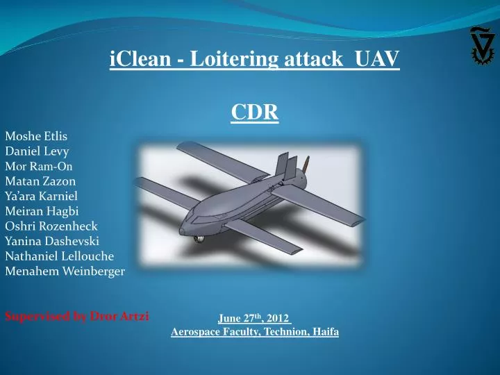
iClean - Loitering attack UAV CDR June 27 th , 2012 Aerospace Faculty, Technion, Haifa. Moshe Etlis Daniel Levy Mor Ram-On Matan Zazon Ya’ara Karniel Meiran Hagbi Oshri Rozenheck Yanina Dashevski Nathaniel Lellouche Menahem Weinberger Supervised by Dror Artzi. Table of Contents.

E N D
iClean - Loitering attack UAV CDR June 27th, 2012 Aerospace Faculty, Technion, Haifa Moshe Etlis Daniel Levy Mor Ram-On Matan Zazon Ya’ara Karniel Meiran Hagbi Oshri Rozenheck Yanina Dashevski Nathaniel Lellouche Menahem Weinberger Supervised by Dror Artzi
Table of Contents • PDR Overview • Remarks from PDR • Airfoil and Propeller Selection • Geometry Improvements • Performance Calculations • Wing Detailed Design • Wings’ Folding Mechanism • System Installation Layout • Weight and Balance • Wind Tunnel Model Design • Wind Tunnel Test • Conclusions and Recommendations
PDR Overview - Customer Specifications • Operational capabilities: • Suicide UAV. • Endurance: 5 hr. • Range: 400 NM (approx. 750 Km) • Man in the loop. • Launching System: Mobile Ground Launcher with as many as • possible UAV's ready to be launched. • Target definition and acquisition: • Target type: Static and mobile. • Truck Target: detection range of 30 Km, recognition of 12 Km. • Target acquisition: Day and Night Capabilities. • Attack capabilities: • Warhead: Approx. 20 Kg. • Attack capabilities: Any angle - vertical or horizontal. • Low Cost UAV unit.
Loiter at 5000 ft at approx. 60 kt Mission Profile Climb to 5000 ft Cruise at 5000 ft at approx. 80 kt Diving at 150 kt Launch BOOM!!
PDR Overview - Chosen Components Sensor: Controp ESP 600C (27 lbs, X15 zoom lens, 0.7-22.6 degrees FOV). Engine: 3W 275 XiB2 (26 HP, 15.5 lbs). Launching Method: Booster rocket (Launched from a canister).
Airfoil Selection Eppler 560 NACA 0012
Airfoil Selection NACA 4412
Propeller Selection Consulting the engine data and information. The chosen engine 3W:275 XiB2 TS (from the PDR). Engine rotation speed : 1000-7000 RPM power : 26 horsepower =~ 19300 watts. Weight: 15.5 lbs=~ 7 Kg. two blade propeller : 26x16 or 26x14 (“) 3 blade propeller : of 22x14 or 24x14 (“).
Propeller Selection - Calculations – Needed Pitch (From our engine data): engine max RPM is 7000 RPM = 116.67 round per second. Max speed at - 180
Propeller Selection - Calculations – Needed Diameter Our propeller is a 2 bladed-back-folding propeller at the size of 25X18. Direction of flight
Geometry Improvements The final geometry for CDR: Geometry as shown at PDR:
Geometry Improvements Old: Wings’ hinges were exposed New: Wings’ hinges are covered Old: 25-75 canard New: 40-60 canard Old: The fuselage becomes thinner in the middle of it and then expends New: The guideline of the fuselage as much as monotonic as possible
UAV’s Properties Weight Airfoil (EPPLER 560) Aspect ratio Reference lift area Fuselage Vertical tail Spans Aerodynamic center’s position
Lift Coefficient’s Properties • Assumptions: • The body as a lift generator componemt:
Lift Coefficient’s Properties Lift coefficient slope Lift coefficient as a function of angle of attack Minimal lift coefficient at height of 0ft and 5000ft Maximal lift coefficient Stall angle Zero lift angle
Drag Coefficient’s Properties • Assumptions:
Drag Coefficient’s Properties Wing’s induced drag coefficient Canard's induced drag coefficient Fuselage's induced drag coefficient UAV’s total induced drag coefficient UAV’s drag
Engine Thrust Assumption: Cruise flight: Maximum thrust Minimum thrust Thrust for cruise flight Velocity • Assumptions: • Cruise flight • Maximal velocity: Minimum velocity (stall) - height of 0ft and 5000ft.
Range & Endurance Assumption & data: Constant: Final results:
Booster Rocket Angle R L F r
Booster Rocket Angle Assumptions and data: Time of opening the wings: Velocity: Density: The mass : :The lift coefficient The acceleration of the booster: Area of wing that creates the lift: The force that booster applies: The lift: The total moment: 27
Wing Detailed Design - Load Distribution The lift load distribution on a trapeze wing:
Wing Detailed Design - Load Distribution Assuming this lift load distribution the resultant force is:
Wing Detailed Design - Flange Area Flanges bl [mm]
Wing Detailed Design - Joint Selection • The selected method is the vertical pin for the Advantages below: • Structural simplicity • Load paths determined with Confidence • Minimum volume of hinge • Simple actuator mechanism • Very few moving parts • Minimum weight
Carbon fiber±45° Wing Detailed Design - Joint Selection A vertical pin through the pivot axis transfer the force-couple from the movable outer wing to the fixed center section Unidirectional Wing's root
Wing Detailed Design - Strength Analysis Force and Moment Calculations: Conclusion from Allowable and Actual Stresses Calculations:
Wing Detailed Design - Strength Analysis Shear Stress Von Mises
Wing Detailed Design - Strength Analysis Factor Calculation:
Wings’ Folding Mechanism Pre Calculations: the average velocity of the UAV during launch time is: Reference areas:
Wings’ Folding Mechanism The wing‘s lift during launch time The wing‘s drag during launch time: Tension Drag
Wings’ Folding Mechanism Drag Direction of flight The wing‘s drag during launch time: Tension Drag
Wings’ Folding Mechanism - Other Related Parts Design Main spring Bearing Movement limiters Connecting rods
Internal Layout Wing & Canard Opening mechanism Motor & Propeller Avionics Integral fuel tank Booster for launch Warhead EO Sensor
Weight and Balance - C.G Location Cg=107.5cm Cp=111.2cm 10% chord stability margin
Wind Tunnel Model Design General instructions: • Max. length: 100 cm. • Max. section area: 2-4% of cell’s section area. • Wing tips should be away from the cell’s walls. • Model shouldn’t be too small in order to get accurate results. The model’s scale will be 1:7.
Wind Tunnel Model Design Canard Wing Steel reinforcement Morse cone Hinge Steel holder Drawn nose