Download
1 / 36
390 likes | 517 Views
Lunar Optical Data Links. Gregory Konesky SGK Nanostructures, Inc. Rutgers Symposium on Lunar Settlements 3-8 June 2007 Rutgers University. Advantages of an Optical Data Link High Bandwidth due to Intrinsically High Carrier Frequency Reduced Component Size as compared to

E N D
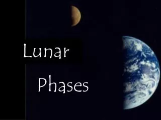
Lunar Optical Data Links Gregory Konesky SGK Nanostructures, Inc. Rutgers Symposium on Lunar Settlements 3-8 June 2007 Rutgers University
Advantages of an Optical Data Link High Bandwidth due to Intrinsically High Carrier Frequency Reduced Component Size as compared to Electronic Counterparts Ability to Concentrate Power in Narrow Beams Very High Gain with relatively Small Apertures Reduction in Transmitted Power Requirements
Two Types of Lunar Optical Links Pan-Lunar: Between two points on the Moon (or orbiting relay satellite) Moon-to-Earth: Direct transmission to the Earth’s surface Satellite reception in Earth orbit followed by retransmission to the surface
Lunar Environment Considerations Absence of significant atmosphere -Path absorption losses minimal -Spreading Loss dominant loss mechanism -No Beam Wander, Scintillation, etc. - No Weather (Clouds, Rain, Fog) Other Environmental Considerations
Top Four Sources of EnvironmentalConcern on the Moon 1. Dust 2. Dust 3. Dust 4. Everything Else
1. Dust Electrostatically attaches to surfaces 2. Dust Atomically sharp, abrasive 3. Dust Wide range of particle distribution size 4. Everything Else Radiation and Solar Flares, Temperature Swings Micrometeorites (and not so “micro”)
Lunar Line-of-Sight Range Limitation Absent topological relief limitations, curvature of the Lunar surface is limiting For a given height, the Lunar Horizon Will be approx. ¼ distance of Earth equivalent Minimal Diffraction Effects (shadows) at Optical wavelengths
Link Budget Block Diagram Moon-to-Earth Optical Data Link
Transmitter Power, 1 W @ 830 nm 0 dBW Transmitter Antenna Gain, 1 m Dia. 131.6 dBi Transmitter Optical Losses - 6.0 dB Space Propagation Losses -315.3 dB Losses in Vacuum 0 dB Spatial Pointing Losses - 1.0 dB Receiver Antenna Gain, 1 m Dia. 131.6 dBi Receiver Optical Losses - 6.0 dB Spatial Tracking Splitter Losses - 1.0 dB Receiver Sensitivity 84.0 dBW Link Margin 17.9 dB Assume: 100 Mbps, 10-6 BER Link Budget Calculation
Aperture Gain 10 cm 111.6 dBi 0.5 m 125.5 dBi 1.0 m 131.6 dBi 1.5 m 135.1 dBi Various Aperture Gains Expressed in dBi
Laser Power dB Value 100 mW - 10 dBW 500 mW - 3 dBW 1.0 W 0 dBW 2.0 W 3 dBW Various Laser Powers Expressed in dBW
Moon - to - Earth Distances and Associated Propagation Losses Minimum: 364,800 km (Propagation Loss = - 314.8 dB) Nominal: 384,00 km (Propagation Loss = - 315.3 dB) Maximum: 403,200 (Propagation Loss = - 315.7 dB)
Associated Beam Diameters Assume: 1 meter Aperture on the Moon 830 nm Wavelength Diffraction-Limited Beam Diameter Near Earth 303 meters (364,800 km) 335 meters (403,200 km)
Earth Satellite vs Earth Surface-Based Reception Satellite Optical Reception Absence of Atmospheric Effects Absorption; Turbulence; Link Availability Higher Cost Construction; Launch; Inaccessibility Higher Tracking Slew Rates Short Reception Window; Higher Hand-Off Rates Greater Point-Ahead Accuracy Need to Re-Broadcast Down to Earth
Link Margin is Maximized by Narrowing Beam Divergence once Lock-In Occurs
Satellite vs Earth-Based Reception- continued Earth-Based Optical Reception Long Reception Window per Station Atmospheric Effects Absorption; Turbulence; Availability; Pulse Spreading Cost Relatively Low Cost; Erecting; Maintaining; Repairing Permits Building More Receivers as a Hedge Against Weather
Increase Beam Divergence to Enhance Detection Probability by Earth-Based Receivers
Narrowing Beam Divergence once Tracking Lock-In Occurs to Maximize Link Margin
Issues with Earth-based Reception Atmospheric Absorption – Link Margin Forward Scattering – Bandwidth Turbulence – Adaptive Optics
Example of Multipath Forward Scattering (Gagliardi and Karp, 1995)
Pulse Stretching due to Multipath Scattering (Gagliardi and Karp, 1995)
Issues Related to Atmospheric Turbulence Naturally Occurring Temperature Variations give rise to Wind Eddies Cause Index of Refraction Changes on the order of 10-6 and are Cumulative Beam Wander – Eddies Larger than Beam Diameter Beam Spreading – Eddies Smaller than Beam Diameter Departure from Wavefront Planarity reduces Bandwidth
Example of relatively Clean Optical Pulse Train and associated Detector Signal
Example of a Distorted Optical Pulse Train and associated Pulse-Stretched Detector Signal
Adaptive Optics Basics Cancels Wavefront Distortion through Phase Conjugation Measures Wavefront Distortion through: Wavefront Sensor Artificial Guide Star Corrects Distortion through: Tilt Mirror Segmented Mirror
Shack – Hartmann Wavefront Sensing Technique (Tyson, 1998)
Examples of Tilt Mirrors (Tyson, 1998)
Example of a 19 Segment Deformable Mirror (Hardy, 1998)
Example of a 512 Segment Deformable Mirror (Tyson, 1998)
Example of a 941Segment Deformable Mirror (Tyson, 1998)
Mt. Diablo to LLNL Optical Data Link Test w/wo Adaptive Optics 28 km slant range and 2.5 Gbit/sec (LFW May 2005)
Conclusions A Moon-to-Earth Optical Data Link can be established with only modest Transmitter Power and Apertures Satellite-based reception provides high availability due to absence of Atmospheric Effects, but at a high cost
Conclusions - continued Earth-based reception prone to Atmospheric Distortions, Reduced Availability, but is a lower cost approach Improve Availability through greater Site Redundancy Correct Distortions with Adaptive Optics Don’t Shoot through Clouds – Pulse Spreading