Download
1 / 52
520 likes | 701 Views
Hardware-Software Partitioning. Definition : Given an application, hw / sw partitioning maps each region of the application onto either a hardware (custom circuits) or a software (microprocessors ), but not both A partition is a mapping of each region to either HW or SW

E N D
Definition: Given an application, hw/sw partitioning maps each region of the application onto • either a hardware (custom circuits) • or a software (microprocessors), • but not both • A partition is a mapping of each region to either HW or SW • Mapping is done to meet certain Design Goals with Constraints Hardware Software Definition
Design Constraints & Goals Performance Power Space Area Schedule Cost Yield
Exploration Space α • E.g. Configurations possible for 30 software components in an application which may be implemented as hardware = 230 = 1Billion • Each component for different tradeoffs may have • Multiple software implementation • Multiple hardware implementation Challenges
15s 15s 5s 25s 10s 12s 10s 5s 8s 5s 10s Application with the Multiple Hardware Software Options Process FIR() ACCUM() SEARCH() Hardware Implementation Options : Area and Execution Time Sw Time: 50s Sw Time: 20s Sw Time: 30s Consider all “middle” implementations Use smallest implementations Use fastest implementations Possible Solutions: 15s 25s Area Budget 10s Best Partition Performance: 5+30+20=55s 10+15+20=45s 25+15+10=50s Acknowledgement: Modified from G. Stitt’s slides in EEL5721
= Hardware execution time of ith component = Software Execution Time of the ith component = Hardware Power of the ith component = Software Power of the ithcomponent Any component is either implemented in Hardware of Software but not in both Mathematical Modeling to arrive at the Optimum H/W-S/W Partition
Dynamic Hardware-Software Partitioning: A First Approach Greg Stitt, Roman Lysecky, Frank Vahid, University of California, Riverside DAC 2003, June 2-6,2003, Anaheim, California, USA
Dynamically • identify and re-implement • critical software kernels, loops etc. to configurable fabric • in order to achieve better performance, lower energy or meet other design goals DynamicHardware-Software Partitioning
EEL5935 Multiple Applications an Illustration
While designing a product usage profile needs to be assumed to give best user experience. However • Usage Profile (Application usage) may be User/code dependent • E.g. MP3, Camera, Video Playback, Call etc. • Usage profile may change over-time • Generic product assuming a certain profile • is optimum for the “assumed” profile but sub-optimal in terms of area or performance for other usage profiles • Profiling in real time is key • usage profile may identify critical kernels • Critical components may be pushed to configurable area • To boost the performance and reduce energy EEL5935 Application Usage Profile: An Illustration Different users have different usage profiles User Mr. Jazz Mr. Luigi Mr. MTB GPS Calls Games Music SMS Data Access
Detect critical code regions Decompile and synthesize them to hardware Place and Route the Hardware onto on-chip configurable logic Update binary to communicate with the logic Dynamic HW/SW Partitioner Requirements • All of the above with on-chip implementable, very lean algorithms Wait ! Did you say on-chip PnR ? You got to be kidding ! Right ?
Partitioning at the binary level • offline or online • Steps • identify critical code sections, high loop sections • Consider assembly code and object code as HW candidates • Push these to configurable hardware • Advantage • Works with any • software compiler • High level language Binary Level Partitioning and Advantage The Paper uses Binary Level partitioning approach. Critical Loops identified and implemented in the Configurable logic
Dynamic Partitioning • Needs to run on a small on-chip partitioning system • Needs to be leanto be able to perform Place and Route etc. on-chip • Higher Level Partitioning Methodologies may be good for offline analysis, but very difficult to implement due to the compute constrain. Why Binary Level Partitioning instead of higher level optimizations ?
EEL5935 HW/SW Partitioning of Software Binary Acknowledgement: Figure taken from G. Stitt, F. Vahid HW/SW Partitioning of Software Binaries ICCAD Nov 2002
EEL5935 System Architecture (Top) Microprocessor and Memory for normal Software application 1. Detects Most Frequently Executed Software region2. Re-implements (1) in the configurable logic Architecture Based on Triscend A7 (60MHz) On chip configurable module
EEL5935 System Architecture (Sub Blocks) Detects Most Frequently executed application-software loops Direct Memory Access Controller to access memory Output 32-bit i/p – o/p register Decompiles and synthesized selected binary regions for HW implementation Input Partitioning Co-Processor Overhead: Not much : Very Lean compared to Main Processor Platform with multiple Main Processors may share single Partitioning co-processor, reducing the overhead further
Simplified Fabric to just support inner loop implementation designed Mapping, placing and routing a design to a general configurable logic fabric is time consuming Simplified Configurable Logic Fabric
No sequential Logic support in the Configurable logic (in the platform chosen) • Constraint: • Loops to be implemented must have single cycle implementable body • Number of loop iterations must be determined before the loop executes, in order to specify the DMA block size request. • Number of iterations may be determined : • Statically in case of constant bounds • Dynamically requires extra instructions to configure the size of the DMA block request before HW execution starts • United States Patent 5,440,245 : Galbraith , et al. August 8, 1995Logic module with configurable combinational and sequential blocks Architecture Limitations
EEL5935 CLF Architecture Either side connect-ability (only at bottom) 4 channel: Given Channel to Given Channel
EEL5935 Tool Flow : Loop Profiler • Detects critical SW regions that should be implemented in HW • Is Non intrusive • Monitors instruction addresses on the memory bus • Increments branch frequency in the cache for a given backward branch • Small cache with a dozen entries • Need to save area and power Reference: Ann Gordon-Ross et. al Frequent Loop Detection Using Efficient Nonintrusive On-Chip Hardware IEEE TRANSACTIONS ON COMPUTERS, VOL. 54, NO. 10, OCTOBER 2005
Converts Software loops into higher level abstraction more suitable for synthesis • Step 1 : Converts each assembly instruction to register transfer • Step 2: Using Register Transfers Builds: • CFG (Control Flow Graph) for software region • DFG(Data Flow Graph) by parsing the Register transfers • Step 3: Applies compiler optimizations to remove overhead due to assembly code and instruction set Decompilation
Function: Maps the memory access of the decompiled loop onto the DMA Architecture • Involves detection of • Reads/ writes • Increment and decrement address updates • Single and block request modes • Remove following from Decompiled loop • Loop counters and exit conditions • Address calculations: As only sequential locations accessed • DMA functioning: • DMA transfers data needed before the loop starts • After HW initialization, HW starts a block request that fetches 1 memory location per cycle in case of a read or write DMA Configuration Tool
Converts each o/p bit into Boolean expression • By traversing the dataflow graphs of the software region • Limitation: • Single cycle executable loop-bodies only • Multi cycle would need behavioral synthesis to schedule loop operations Register Transfer Synthesis
Converts Boolean equations into a netlist • Boolean equations transformed into DAG (directed acyclic Graph) of the Boolean Logic network • Internal Nodes of DAG correspond to simple logic gates (AND/OR/INV, XOR) • Logic minimization • Light weight suited for on-chip execution • Applied at each node starting with the input nodes, while traversing through the network • Uses single expand phase to achieve good optimization • Tech Mapping • Traverses DAG starting from output nodes • Combines nodes that may create 3 i/p 1 o/p LUT • Further combine nodes (where possible ) to form 3 i/p 2 o/p LUTs Logic Synthesis Tech Mapping P&R
Step 1: Determine relative placement of LUTs to one another • by determining the critical path, and placing it on a horizontal row • Step 2 : For remaining non-placed nodes place as per dependency (i/p or o/p) w.r.t. placed • Place above for inputs to Placed nodes • Place below for outputs from Placed nodes • Step 3: Place in the Configurable Logic LUT Placement Steps
Simple Greedy algorithm • Routes wires in most direct fashion • Route the wires between input nodes and LUTs • Route wires from LUTs to outputs • Route wires connecting LUTs together • Routing decisions at Switch Matrices for within conifugrable logic fabric Routing
Combines • the Placed and routed hardware description with the DMA configuration information into a single bit file • Bitfile can be used to initialize the configurable logic Bitfile Creation
Update software binaries to utilize HWfor loops • Replace original software instruction for loop to a jump to HW initializing code • Initializing code sends HW enable signal through Memory mapped register • Code followed up with microprocessor power down trigger • Upon finishing HW asserts completion signal causing a software interrupt • Software interrupt wakes the microprocessor • Jump instruction at the end of the hardware initialization code to the end of the original software loop Bitfile modification
EEL5935 Tool : Performance and Area overhead • Typical tools for De-compilation, synthesis, and Place and Route need huge LSF machines • Designed tool very light weight and geared towards partitioning co-processor Data Size: Memory required for the tool execution Time : Execution time of each tool considering 60MHz clock and 1.5 cycle/Instruction
Results Definitions: Loop Time Perc: Percentage of total software time, spent in the implemented loops Loop Size Perc: Percentage of the total instructions that the loop required Ideal Speedup: Speedup assuming HW implemented loops are executing in Zero time. Sw Loop Time: Time required by the loop if completely in software HW Loop Time: Time when loop implemented in HW
Dynamic HW/SW Partitioning offers advantages over traditional approach: • Transparent i.e. Benefits of partitioning even with regular software flows • Can adapt as per actual usage profile • Upto2.6 average speedup Conclusion
Power required by the partitioning module and the HW running specified as 10-20% of total power • Power data for individual modules not presented • Realistic loops have sequential logic and may not be always single cycle • Extend implementation on sequential logic compatible CLF • Extend to include mutli cycle loops • Applications seem too biased especially “url”, with 80% loop time with just 0.1% loop area overhead • Place and Route, synthesis would have been difficult to do on single partitioning chip: • Today as on 2013 it should be possible to interface the modules with the cloud computing. I would rather have a complex algorithm run to get best suited partition profile, on a cloud network than to try small tricks with the lean co-processors • This would be application dependent Areas of Improvement of Future Work
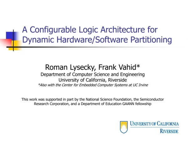
A Study of the Speedups and Competitiveness of FPGA Soft Processor Cores using Dynamic Hardware/Software Partitioning Roman Lysecky, Frank Vahid, University of California, Riverside Design, Automation and Test in Europe Conference and Exhibition (DATE’05)
Hard-Processor • Pros: Performance • Cons: Flexibility • Soft-processors • Pros: Flexibility • Cons: Degraded Performance and Energy Consumption Motivation (1/2) Can we leverage benefits of both using Warp Processing ?
Warp Processing : Technique for • optimizing a software application • by dynamically and transparently re-implementing “critical software kernels” as custom circuits in on-chip configurable logic • Study MicroBlaze based Warp processing System to • Eliminate the performance and energy overhead of a soft-processor compared to a hard-processor Motivation (2/2)
Hard-core • Excellent Packaging and communication with the FPGA • Lower Power and Higher Performance than Soft-core • E.g. : Triscend, Atmel, Altera’s Excalibur, Virtex* with PowerPCs • Soft-core • Lower Part cost • Extreme Flexibility during design process • Adding custom instructions or including/ excluding particular data-path coprocessors • Quickly integrate the processor within a FPGA • Varying number of processors as per need • E.g. NIOS, NIOS II …, Picoblaze, Microblaze FPGA single-chip Systems: Hard-core Vs Soft-core Use Hardware / Software Partitioning Techniques to alleviate Power and Performance overhead of Soft Processors
MicroBlaze Soft Processor Core Specify system Architecture and configure MicroBlaze Xilinx Platform Studio Tools Synthesizes design Bitstream Software Libraries MicroBlaze – 32bit softcore by Xilinx LMB – Local Memory Bus BRAM – Block RAM : User Defined Size OPB – On-Chip Peripheral Bus Compile Application Final System Bitstream
User Configurable options • Tailor processor’s functionality as per the design need • Configurable Instructions and data caches • Incorporate additional hardware: • Hardware multiplier ( mul instructions) • Hardware Divider ( div instructions ) • Barrel Shifter (bs and bsi instructions) • Hardware bit manipulations and absolute plus Key features of MicroBlaze
brev (Powerstone benchmark suite) • Critical kernel performs bit reversal heavily relying on shift operations • Software only Implementation (without mul or barrel shift) • N-bit shift by using n-successive add operations • Configurable Hardware implementation • 2.1X speed up • “matmul” • Critical Region : Matrix multiplication • Hardware Multiplier provides 1.3X speedup Applications analyzed
MicroBlaze-based Warp Processor Implement critical Kernels in WCLA as cutom HW Identify Critical Kernels in execution time WCLA – Warp Configurable Logic Architecture
Warp ConfigerableLogic Architecture for Dynamic HW/ SW Partitioning • DADG: Data Address Generator • Used for any memory accesses to/for Configurable logic • LCH: Loop Control Hardware • Handles loops and controls executions Reg 0, Reg 1 Reg 2: i/p to CLF /or MAC (as per mapping) Outputs from the configurable logic stored in Registers
MicroBlaze Multi-processor warp processing system • Mutliple Soft-cores may be incorporated within a single FPGA • Limited only by the FPGA Size • Multi-processor Warp Processing system may share a common DPM and WLCA and HW/SW partitioning may be done in round robin manner • No Overhead due to additional DPMs • Partitioning tools may be implemented as software tasks running in one of the cores
Execution Time and Power studied • Embedded systems applications chosen from Powerstone and EEMBC benchmark suites studies • MicroBlaze processor core implemented on Spartan3 FPGA • Barrel Shifter and Multiplier configured in Hardware • Note: MicroBlaze max frequency 85MHz; However FPGA circuits may run upto 250MHz Experimental Setup
Profiling Simulation Soft App 2 Soft App 1 Soft App n Xilinx Microprocessor Debug Engine MicroBlaze Inst Trace 1 Inst Trace n Inst Trace 2 Simulate On-chip Profiler Behavior Critical Region
Energy Equations Total Energy Consumed = Energy Consumed by HW in Configurable Logic = Energy Consumed by Microblaze =
Performance / Power Simulation MicroBlaze and system Component (excluding WCLA) Execution Traces of critical regions Critical Regions Execute HW Circuits (VHDL model for WCLA) for each partitioned Critical Region Xilinx XPower VHDL Synopsys Design Compiler UMC 0.18um Library Dynamic Power Static Power Determine final application performance Synthesis Configurable HW Power MicroBlaze Power
Results ARM execution determined using Simple Scalar
Warp processors (with soft-core), by pushing critical software kernels to the CFG can provide • Flexibility of the Soft-core • Due to soft-core implementation • Competitiveness of a Hard-core processors (as ARM) • Performance of the order of the Hard-core • By leveraging special Configured HW • 5.8X (average) improvement (with MicroBlaze) • Eliminates Energy Overhead • By faster execution due to dedicated hardware and trimming down the soft-processor to perfectly fit design needs • Average Energy reduction ~ 57% • Opened Avenues for Soft-core processors which would not have been feasible previously due to energy/performance Conclusion
Real processing systems do not just do a execute just a single application at a time • For realistic data, multiple applications should be run simultaneously • Explore Parallel Processing architecture further • Power Estimation Data • Estimation is good • It would be good to see real data as well • Online Profiler has a dozen entries • Number of entries should be configurable to avoid local maxima • Instead of simplified configurable logic fabric, how about using underlying FPGA physical fabric • Algorithm to come up with re-partitioning time interval should be worked up Areas of Improvement & Future Work