Download
1 / 17
170 likes | 416 Views
TES Bolometer Array with SQUID readout for Apex. V. Zakosarenko, T. May, R. Stolz, H.-G. Meyer, Institute for Physical High Technology, Jena E. Kreysa, W. Esch, Max Planck Institute for Radioastronomy, Bonn. The work is supported by the German BMBF under the contract No. 05 AA2PC1/3. Laboca.

E N D
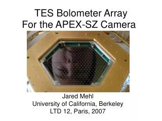
TES Bolometer Array with SQUID readout for Apex V. Zakosarenko, T. May, R. Stolz, H.-G. Meyer, Institute for Physical High Technology, Jena E. Kreysa, W. Esch, Max Planck Institute for Radioastronomy, Bonn The work is supported by the German BMBF under the contract No. 05 AA2PC1/3.
Laboca Project purpose: Large Bolometer Camera (Laboca) with 300 pixel for sub-millimeter range for Atacama Pathfinder Experiment (APEX) on array of 12m-telescopes in Chili , Atacama
Bolometer Principles Infrared power Peiwt dT dR dI Thermistor = transition edge sensor (TES)
The transition temperature Tc is slightly above the bath temperature T0 . • Due to the power dissipation • PBIAS = VBIAS2/RW = (TC-T0)/G • the thermistor warms up to TC . • The working point is stable: • T R PBIAS T • Electro-Thermal Feedback (ETF) Electro Thermal Feedback Transition edge sensor with voltage bias Resistance Working point Rw T0 Tc Temperature
Signal Response Current response Sharpness of the transition Effective time constant Open loop gain L>>1 ; wt << 1
TES Bilayer Au-Pd (8 nm) Proximity bilayer with TC~ 0.5K Mo (60 nm)
7-pixel Array Si N membrane ~1µm thick with Ti absorber film on the back side Si wafer Au ring Thermistor (TES) 7-pixel array chip mounted in the Cu holder plate (1,5 cm x 1,5 cm) Nb wiring
SQUID current sensors SQUID current sensor chip µ-metal shield SQUID holder with 4 mounted current sensors
Measuring System SQUID holder with 4 current sensors. The µ-metal shield is not installed. Superconducting bolometer chamber (Al) with7-pixel horn array 3He stage with sorption pump (300mK) 1.5K pot of 4He cryostat
First Light 30m - radiotelescope of IRAM on Pico Veleta in Spain, Sierra Nevada. Cryostat with TES bolometers in telescope cabin
First Results The whole system worked stable in the cabin. But: bad weather (snow) Power calculated as IBIAS x RBIAS x Si Response of the bolometers on the change of black body temperature (77K 300K)
Next Step LABOCA: Large Bolometer Camera: 300 pixel on 4 inch wafer Laboca should be ready in the middle of the year 2005!
Multiplexing • Two possibility: • parallel readout • 300 current sensors each in separate packaging, ~1250 wires to room temperature electronics, 300 FLL electronics. • low risk (familiar way) • mechanical complexity, thermal last, tooexpensive ! • b) multiplexing • 300 SQUID integrated on the wafer with bolometers, ~30 SQUID amplifier in separate packaging, ~200 wires to room temperature, 30 FLL electronics, and digital controller . • less expensive • new development (challenge !)
TES TES TES TES RBIAS RBIAS RBIAS RBIAS Time Domain MUX TES bias Digital control bias switches Bias Sinch Amplifier SQUID Active SQUID RESET FLL electronics, Out 300K 0.3K Feedback 1.5K
Test of the MUX Electronics Sampling frequency 100 kHz Sampling frequency 5 kHz 6 separate SQUIDs, SQUID-array as amplifier, the simplest FLL with two operational amplifiers
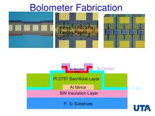
Integrated Bolometer First samples are fabricated. Tests in the laboratory will be performed in the next weeks.
Conclusions • 7 pixel TES bolometer array with SQUID readout shows stable operation in real environment in telescope cabin. • 7 pixel TES bolometer array with integrated SQUID is ready for test. • Time domain multiplexing operates. Optimization of bandwidth and noise figure is in progress. • Great challenge to perform the proposed schedule.