Download
1 / 29
540 likes | 1.01k Views
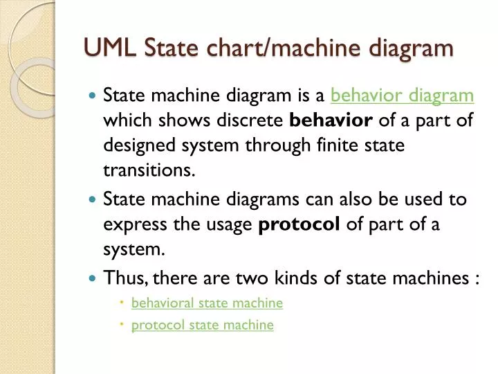
UML State chart/machine diagram. State machine diagram is a behavior diagram which shows discrete behavior of a part of designed system through finite state transitions. State machine diagrams can also be used to express the usage protocol of part of a system.

E N D
UML State chart/machine diagram • State machine diagram is a behavior diagramwhich shows discrete behavior of a part of designed system through finite state transitions. • State machine diagrams can also be used to express the usage protocol of part of a system. • Thus, there are two kinds of state machines : • behavioral state machine • protocol state machine
The following nodes and edges are typically drawn in state machine diagram: behavioral state, behavioral transition, protocol state, protocol transition, different pseudostates.
Behavioral State Machine • Behavior is modeled as a traversal of a graph of state nodes connected with transitions. • Transitions are triggered by the dispatching of series of events. During the traversal, the state machine could also execute some activities.
Vertex • Vertex is named element which is an abstraction of a node in a state machine graph. In general, it can be the source or destination of any number of transitions. • Subclasses of vertex are: • state • Pseudostate • State is a vertex which models a situation during which some (usually implicit) invariant condition holds.
State • State in behavioral state machines models a situation during which some (usually implicit) invariant condition holds. • The invariant may represent a static situation such as an object waiting for some external event to occur. However, it can also model dynamic conditions such as the process of performing some behavior (i.e., the model element under consideration enters the state when the behavior commences and leaves it as soon as the behavior is completed).
State • The UML defines the following kinds of states: • simple state, • composite state, • submachine state.
Simple State • A simple state is a state that does not have substates - it has no regions and it has no submachine states. Simple state Waiting for Customer Input.
Simple state • Simple state may have compartments. The compartments of the state are: • name compartment • internal activities compartment • internal transitions compartment
Simple state • Name compartment holds the (optional) name of the state • Internal activities compartment holds a list of internal actions or state (do) activities (behaviors) that are performed while the element is in the state. • The activity label identifies the circumstances under which the behavior specified by the activity expression will be invoked. The behavior expression may use any attributes and association ends that are in the scope of the owning entity. For list items where the expression is empty, the slash separator is optional.
Activities in state diagrams(Lethbridge) • An activity is something that takes place while the system is in a state. • It takes a period of time. • The system may take a transition out of the state in response to completion of the activity, • Some other outgoing transition may result in: • The interruption of the activity, and • An early exit from the state. Chapter 8: Modelling Interactions and Behaviour
Actions in state diagrams(Lethbridge) • An action is something that takes place effectively instantaneously • When a particular transition is taken, • Upon entry into a particular state, or • Upon exit from a particular state • An action should consume no noticeable amount of time Chapter 8: Modelling Interactions and Behaviour
Internal activities compartment • Simple state Waiting for Customer Input with name and internal activities compartments.
Simple state • Several labels are reserved for special purposes and cannot be used as event names. The following are the reserved activity labels: • entry (behavior performed upon entry to the state) • do (ongoing behavior, performed as long as the element is in the state) • exit (behavior performed upon exit from the state)
Simple state • Internal transition compartment contains a list of internal transitions, where each item has the form as described for trigger. • Each event name may appear more than once per state if the guard conditions are different. • The event parameters and the guard conditions are optional. If the event has parameters, they can be used in the expression through the current event variable.
Composite state • Composite state is defined as state that has substates (nested states). • Simple composite state contains just one region • Orthogonal composite state has more than one region Simple composite state Serving Customer has two substates.
Composite state • Composite state may have compartment • The compartments of the state are: • name compartment • internal activities compartment • internal transitions compartment • decomposition compartment
Decomposition compartment • Decomposition compartment shows composition structure of the state as a nested diagram with regions, states, and transitions. For convenience and appearance, the text compartments may be shrunk horizontally within the graphic region. • In some cases, it is convenient to hide the decomposition of a composite state. For example, there may be a large number of states nested inside a composite state and they may simply not fit in the graphical space available for the diagram.
Decomposition compartment Composite state Serving Customer with decomposition hidden. A composite state may have one or more entry and exit points on its outside border or in close proximity of that border (inside or outside).
Submachine State • A submachine state specifies the insertion of the specification of a submachine state machine. • The state machine that contains the submachine state is called the containing state machine. • The same state machine may be a submachine more than once in the context of a single containing state machine.
Pseudostate • Pseudostates are typically used to connect multiple transitions into more complex state transitions paths. • Pseudostates include: • initial pseudostate • terminate pseudostate • entry point • exit point • choice • join • fork • junction • shallow history pseudostate • deep history pseudostate
Initial Pseudostate • An initial pseudostate represents a default vertex that is the source for a single transition to the default state of a composite state. • There can be at most one initial vertex in a region. • The outgoing transition from the initial vertex may have a behavior, but not a trigger or guard. • An initial pseudostate is shown as a small solid filled circle. Initial pseudostate transitions to Waiting for User Input state
Terminate Pseudostate • Terminate pseudostate implies that the execution of this state machine by means of its context object is terminated. • The state machine does not exit any states nor does it perform any exit actions other than those associated with the transition leading to the terminate pseudostate. • A terminate pseudostate is shown as a cross. Transition to terminate pseudostate
Entry Point • Entry point pseudostate is an entry point of a state machine or composite state. • In each region of the state machine or composite state it has at most a single transition to a vertex within the same region. • An entry point is shown as a small circle on the border of the state machine diagram or composite state, with the name associated with it. Entry point user entry
Exit Point • Exit point pseudostate is an exit point of a state machine or composite state. • An exit point is shown as a small circle with a cross on the border of the state machine diagram or composite state, with the name associated with it. Exit point user exit
Choice • Choice pseudostate realizes a dynamic conditional branch. It evaluates the guards of the triggers of its outgoing transitions to select only one outgoing transition. • The decision on which path to take may be a function of the results of prior actions performed in the same run-to-completion step. • A choice pseudostate is shown as a diamond-shaped symbol. Choice based on guards applied to the value inside diamond
Fork • Fork pseudostate vertices serve to split an incoming transition into two or more transitions terminating on orthogonal target vertices (i.e., vertices in different regions of a composite state). • The segments outgoing from a fork vertex must not have guards or triggers. • The notation for a fork is a short heavy bar. The bar may have one or more arrows from the bar to states. A transition string may be shown near the bar. Fork splits transition into two transitions
Join • Join pseudostate merges several transitions originating from source vertices in different orthogonal regions. • The transitions entering a join vertex cannot have guards or triggers. • The notation for a join is a short heavy bar. The bar may have one or more arrows from source states to the bar. A transition string may be shown near the bar. Join merges transitions into single transition
Junction • Junction pseudostate vertices are vertices that are used to chain together multiple transitions. • They are used to construct compound transition paths between states. • For example, a junction can be used to converge multiple incoming transitions into a single outgoing transition representing a shared transition path (this is known as a merge). • A junction is represented by a small black circle.
Final State • Final state is a special kind of state signifying that the enclosing region is completed. • If the enclosing region is directly contained in a state machine and all other regions in the state machine also are completed, then it means that the entire state machine is completed. • A final state is shown as a circle surrounding a small solid filled circle. Transition to final state.