Download
1 / 8
80 likes | 180 Views
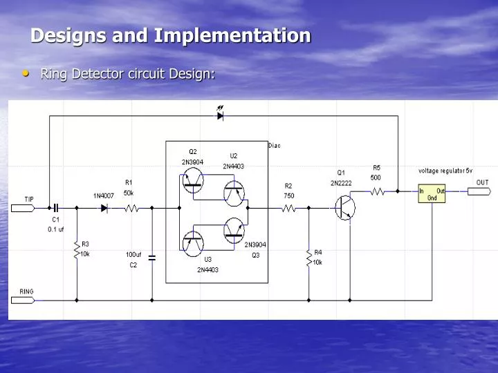
Designs and Implementation. Ring Detector circuit Design:. Description: - The above circuit can be directly connected to the phone line via the TIP and RING wires (green and red), or it can be connected in parallel with a telephone.

E N D
Designs and Implementation • Ring Detector circuit Design:
Description: - The above circuit can be directly connected to the phone line via the TIP and RING wires (green and red), or it can beconnected in parallel with a telephone. - When the phone rings, capacitor C2 will charge until the break over voltage of the diac diode is reached turning on the transistor Q1. As Q1 turns on and off, when a ring signal is detected, a series of pulses will be send to the voltage regulator. -The output results in a 5 volt square wave every time a pulse is detected, an LED also flashes to indicate that the ring tone is being detected.
DTMF (Dual Tone Multiple Frequency): DTMF diagram:DTMF chip pin layout:
We know that the tone controlled system is implemented using a feature of commercial phones called Dual Tone Multiple Frequency (DTMF). In this Feature, the tones generated by the keys on a telephone or mobile are actually a combination of 2 frequencies: a high group and low group frequency that are sent simultaneously. There are eight standard frequencies and the yare distributed as we see in the next slide
Description of the Frequency tones: • Standard and commercial telephones or mobiles generally include digits 0 to 9 with the characters * and #. Each number or character on a keypad is given a set of low and high frequency. Theses frequencies are common in all phones and it can be used to input commands. Since telephones are frequently used as input sources, decoding such tones is fairly common. That leads us to think of implementing and designing band-pass filters, one for each frequency. Band-pass filters allow only a certain range of frequencies to pass through, and block all frequencies lower or higher that the designated range. • Since we know that implementing 8 band-pass filters will be time-consuming we decided to purchase a DTMF chip (MT 8870 D ) which fulfilled the goal we need.
Description of the DTMF MT 8870 D function: The MT8870D/MT8870D-1 monolithic DTMF receiver offers: - Small size - Low power consumption - High performance • It consists of a band-split filter section, which separates the high and low group tones frequencies. • Following the filter section is a decoder employing digital counting techniques to determine the frequencies of the incoming tones and to verify that they correspond to standard DTMF frequencies.