Download
1 / 15
160 likes | 380 Views
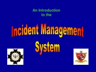
An Introduction to the R3 19 inch Rack. The R3 control system comprises a number of different plug in modules, each of which is dedicated to a particular function within the complete control panel. Modules cover all requirements - Fire detection Alarm signalling Gas detection Extinguishing

E N D
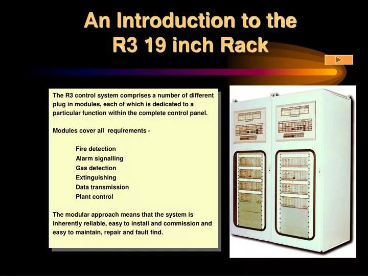
An Introduction to the R3 19 inch Rack • The R3 control system comprises a number of different plug in modules, each of which is dedicated to a particular function within the complete control panel. • Modules cover all requirements - • Fire detection • Alarm signalling • Gas detection • Extinguishing • Data transmission • Plant control • The modular approach means that the system is inherently reliable, easy to install and commission and easy to maintain, repair and fault find.
Common Control Module • Every R3 system must contain a Common Control Module. • This module incorporates all executive action user controls. • There are two types - • K1321 - Conventional systems only • K1339 - Both analogue addressable and conventional systems • The Common Control Module is always fitted in the right hand module position of its designated rack.
K1339 Common Control Module • User Controls • System Messages • User Indications • Engineer Functions • Printer Output • Event Memory • Network Data Output
K1339 Common Control Module • User Controls • Silence Alarms • Reset System • Test Alarms • Silence Buzzer • Test Lamps
K1339 - Silence Alarms Press Key 1 Alarms silence “Alarms Silenced” indicator lights Panel buzzer sounds
K1339 - System Reset Press Key 2 Message display clears “Alarms Silenced” indicator goes out Buzzer stops System is reset
K1339 - 1 Fire Message Event message shows loop number and device address with device type and status in line 1. Second line is a user defined description of the area where the device is located.
K1339 - 2 Fire Messages First event remains in lines 1 and 2. Second event is shown in lines 3 and 4. (Example shown where smoke is detected on stairs and a break glass is operated later.).
K1339 - Further Events First event remains in lines 1 and 2. Second event is shown in lines 3 and 4. “More Data” LED is lit. Pressing key 6 scrolls next event into lines 3 and 4.
K1339 - More Data Display First event remains in rows 1 and 2 of display. Pressing key 6 scrolls later events into the bottom 2 lines until all events have been viewed.
K1339 Common Control Module • Engineer Controls • (via Access Code) • Time and Date • Text Messages • Device Isolate • Printer Dump • Memory
K1339 Common Control Module -Engineer Controls • Text Messages • Sensors • Zones • Indication Zones • Inputs
K1339 Common Control Module -Engineer Controls • Device Isolate • Single / Range Isolate • Single / Range De-isolate • De-isolate All • List Isolations • Print Isolations
K1339 Common Control Module -Engineer Controls • Printer • Printer Dump • Clear Print Queue • Normal Print • Reverse Print
K1339 Common Control Module • Event Memory • View All Events in Reverse Order