Download
1 / 51
520 likes | 732 Views
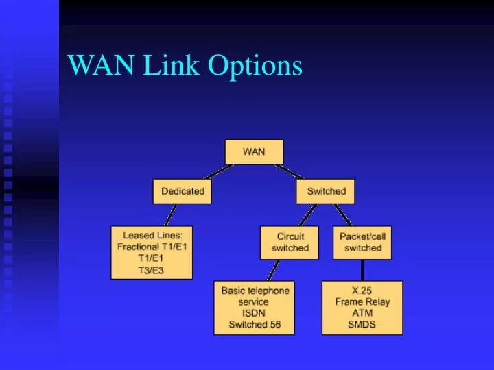
WAN Link Options. Common WAN Data-Link Encapsulations. WAN data-link layer defines how data is encapsulated for transmission to remote sites. ISDN. Developed by telecom companies Uses existing telephone wiring but provides higher speeds than analogue modems Digital service

E N D
Common WAN Data-Link Encapsulations • WAN data-link layer defines how data is encapsulated for transmission to remote sites
ISDN Developed by telecom companies Uses existing telephone wiring but provides higher speeds than analogue modems Digital service Alternative to Frame Relay and E1/T1 lines for corporate users Alternative to analogue modem for home users
Advantages of ISDN • Carries variety of traffic types • Faster call set-up than analogue PSTN • Faster data transfer rate than analogue modem
ISDN Services - BRI vs. PRI • BRI: • 2B + D • 2 x 64Kbps data + 16Kbps signalling • Uses normal copper twisted pair telephone wire • PRI: • 30B + D • 30 x 64Kbps data + 64Kbps signalling • Uses 2.048Mbps T1 line
ITU-T standards for ISDN • I.430 – BRI; I.431 – PRI (Physical Layer) • Q.920, Q.921 – D channel signalling (Data Link Layer) • I.450 (aka Q.930), I.451 (aka Q.931) – circuit-switched and packet-switched connections (Network Layer)
ISDN Switch Types • ISDN standardised, but standard is ambiguous • So different vendors implementations may not work together • Check what switch type your telecom provider is using, and make sure to buy equipment that is compatible • Also, may need SPID from telecom provider when configuring ISDN equipment
ISDN Configuration Tasks • Global configuration • Select switch type • Specify traffic to trigger DDR call • Interface Configuration • Select interface specifications • Configure ISDN addressing • Optional Feature Configuration
Useful Diagnostic / Monitoring Commands • ping / telnet • show dialer • show isdn active • show isdn status • show ip route • debug isdn q921 • debug dialer • clear interface
ATM Asynchronous Transfer Mode (aka cell relay) Designed to carry voice, video, data Faster than X.25, more streamlined than frame relay Very high transfer speeds, several orders of magnitude greater than frame relay Broadcast service
ATM Standards • ATM originally developed by ITU-T • Extended by the ATM Forum: • User-to-Network Interface (UNI versions 2.0, 3.0 and 3.1) • Public-Network Node Interface (P-NNI) • LAN Emulation (LANE)
Bytes 5 48 Header User Data ATM Cells • Small, fixed-length packets of this format: • Suited to transferring voice and video, because small packets have small delays
Virtual Path Virtual Channel Transmission Path ATM Services • Basic unit of service is a virtual channel – identified by VCI • Virtual path identified by VPI • VCIs and VPIs have only local significance across a link, remapped at each switch
ATM Adaptation Layers • AAL1 • connection-oriented service, • suitable for handling circuit-emulation applications, such as voice and video conferencing • circuit-emulation service also accommodates the attachment of equipment currently using leased lines to an ATM backbone network.
ATM Adaptation Layers • AAL3/4 • supports both connection-oriented and connectionless data • designed for network service providers and is closely aligned with Switched Multimegabit Data Service (SMDS) • AAL3/4 is used to transmit SMDS packets over an ATM network
ATM Adaptation Layers • AAL5 • the primary AAL for data • supports both connection-oriented and connectionless data • used to transfer most non-SMDS data, such as classical IP over ATM and LAN Emulation (LANE).
ATM Addressing • Based on structure of OSI network service access point (NSAP) addresses • Own addressing scheme – not related to IP • So an ATM device running TCP/IP must have an ATM address and an IP address • ATM ARP required to map higher layer addresses to ATM addresses • ATM networks also run their own routing protocols
ATM Connections • Point-to-point connections • Between two ATM end-systems • Unidirectional or bidirectional • Point-to-multipoint • For multicast from one ATM end-system to multiple other ATM end-systems • Unidirectional • Cell replication done within ATM network by the ATM switches at branch points
ATM Quality of Service • Traffic Contract • Specifies envelope with values for peak bandwidth, average sustained bandwidth, burst size… • Traffic Shaping • Use of queues to constrain data bursts, limit peak data rate, smooth jitters to ensure traffic fits envelope specified by traffic contract • Traffic Policing • Used by switches to enforce traffic contract • Traffic outside contract parameters can be dropped based on CLP (cell-loss priority) bit
LAN Emulation (LANE) • Emulates a LAN (IEEE 802.3 or 802.5) over ATM • Defines a service interface to network-layer protocols identical to that of existing LANs • Makes the ATM network act like an Ethernet or Token-Ring LAN • Does not attempt to emulate the MAC protocol of the specific LAN concerned
GSM: Overview • Formerly: Groupe Spéciale Mobile (founded 1982) • Now: Global System for Mobile Communication • Pan-European standard (ETSI, European Telecommunications Standardisation Institute) • Simultaneous introduction of essential services in three phases (1991, 1994, 1996) by the European telecommunication administrations (Germany: D1 and D2) • Seamless roaming within Europe possible • Today many providers all over the world use GSM (more than 130 countries in Asia, Africa, Europe, Australia, America) • More than 100 million subscribers
bearer services MS GSM-PLMN transit network (PSTN, ISDN) source/ destination network TE MT TE R, S Um (U, S, R) tele services GSM: Mobile Services • GSM offers • several types of connections • voice connections, data connections, short message service • multi-service options (combination of basic services) • Three service domains • Bearer Services • Telematic Services • Supplementary Services
Tele Services • Telecommunication services that enable voice communication via mobile phones • All these basic services have to obey cellular functions, security measurements etc. • Offered services • Mobile telephonyprimary goal of GSM was to enable mobile telephony offering the traditional bandwidth of 3.1 kHz • Emergency numbercommon number throughout Europe (112); mandatory for all service providers; free of charge; connection with the highest priority (preemption of other connections possible) • Multi-numberingseveral ISDN phone numbers per user possible
Bearer (Data) Services • Telecommunication services to transfer data between access points • Specification of services up to the terminal interface (OSI layers 1-3) • Different data rates for voice and data (original standard) • data service (circuit switched) • synchronous: 2.4, 4.8 or 9.6 kbit/s • asynchronous: 300 - 1200 bit/s • data service (packet switched) • synchronous: 2.4, 4.8 or 9.6 kbit/s • asynchronous: 300 - 9600 bit/s
Bearer Services (Cont’d) • Additional services • Group 3 fax • Voice mailbox (implemented in the fixed network supporting the mobile terminals) • Electronic mail (MHS, Message Handling System, implemented in the fixed network) • Short Message Service (SMS)alphanumeric data transmission to/from the mobile terminal using the signaling channel, thus allowing simultaneous use of basic services and SMS
Supplementary services • Services in addition to the basic services, cannot be offered stand-alone • Similar to ISDN services except lower bandwidth due to the radio link • May differ between different service providers, countries and protocol versions • Important services • identification: forwarding of caller number • suppression of number forwarding • automatic call-back • conferencing with up to 7 participants • locking of the mobile terminal (incoming or outgoing calls)
Handover • Radio and fixed links required are not permanently allocated for the duration of a call. • Handover is the switching of an on-going call to a different channel or cell. • There are four different types of handover in the GSM system, which involve transferring a call between: • Channels (time slots) in the same cell • Cells (Base Transceiver Stations) under the control of the same Base Station Controller (BSC) • Cells under the control of different BSCs, but belonging to the same Mobile services Switching Centre (MSC) • Cells under the control of different MSCs
4 types of handover 1 2 3 4 MS MS MS MS BTS BTS BTS BTS BSC BSC BSC MSC MSC
Handover (Cont’d) • Handovers can be initiated by either the mobile or the MSC (as a means of traffic load balancing) • Mobile scans the Broadcast Control Channel of up to 16 neighbouring cells, forming list of best candidates for possible handover • This information is passed to the BSC and MSC, at least once per second, and is used by the handover algorithm. • The algorithm for when a handover decision should be taken is not specified in the GSM recommendations.
Handover decision receive level BTSold receive level BTSold HO_MARGIN MS MS BTSold BTSnew
Handover Algorithm • The 'minimum acceptable performance' algorithm: • Gives precedence to power control over handover – increases mobile’s power level when signal degrades beyond a certain point • If further power increases do not improve the signal, then a handover is considered • This is the simpler and more common method, but creates 'smeared' cell boundaries when a mobile transmitting at peak power goes beyond its original cell boundaries into another cell.
Handover Algorithm • The 'power budget' method: • This uses handover to try to maintain or improve a certain level of signal quality at the same or lower power level. It thus gives precedence to handover over power control • It avoids the 'smeared' cell boundary problem and reduces co-channel interference, but it is quite complicated
Handover procedure MSC MS BTSold BSCold BSCnew BTSnew measurement report measurement result HO decision HO required HO request resource allocation ch. activation ch. activation ack HO request ack HO command HO command HO command HO access Link establishment HO complete HO complete clear command clear command clear complete clear complete
Security in GSM • Security services • access control/authentication • user SIM (Subscriber Identity Module): secret PIN (personal identification number) • SIM network: challenge response method • confidentiality • voice and signaling encrypted on the wireless link (after successful authentication) • anonymity • temporary identity TMSI (Temporary Mobile Subscriber Identity) • newly assigned at each new location update (LUP) • encrypted transmission • 3 algorithms specified in GSM • A3 for authentication (“secret”, open interface) • A5 for encryption (standardized) • A8 for key generation (“secret”, open interface) • “secret”: • A3 and A8 available via the Internet • network providers can use stronger mechanisms
Terminal Security • GSM terminal identified by unique IMEI number • A list of IMEIs in the network is stored in the Equipment Identity Register (EIR) • Status returned in response to IMEI query to EIR: • White-listed - terminal is allowed to connect to the network. • Grey-listed - terminal is under observation from the network for possible problems. • Black-listed - terminal has either been reported stolen, or is not type approved. Terminal is not allowed to connect to the network
Data services in GSM I • Data transmission standardized with only 9.6 kbit/s • advanced coding allows 14,4 kbit/s • not enough for Internet and multimedia applications • HSCSD (High-Speed Circuit Switched Data) • already standardized • bundling of several time-slots to get higher AIUR (Air Interface User Rate)(e.g., 57.6 kbit/s using 4 slots, 14.4 each) • advantage: ready to use, constant quality, simple • disadvantage: channels blocked for voice transmission